IP loop distribution type and width processing method

A processing method and distributed technology, applied in the field of telecommunications, can solve problems such as insufficient bandwidth reuse, no consideration of destination nodes, unreasonable processing methods, etc., and achieve high comprehensive bandwidth utilization and strong self-healing ability , optimize the effect of local bandwidth

A processing method and distributed technology, applied in the field of telecommunications, can solve problems such as insufficient bandwidth reuse, no consideration of destination nodes, unreasonable processing methods, etc., and achieve high comprehensive bandwidth utilization and strong self-healing ability , optimize the effect of local bandwidth

CN1466391AInactive Publication Date: 2004-01-07SHENZHEN HUAWEI TECHNOLOGIES SOFTWARE CO LTD

Image

  • IP loop distribution type and width processing method
  • IP loop distribution type and width processing method
  • IP loop distribution type and width processing method

Examples


Embodiment Construction

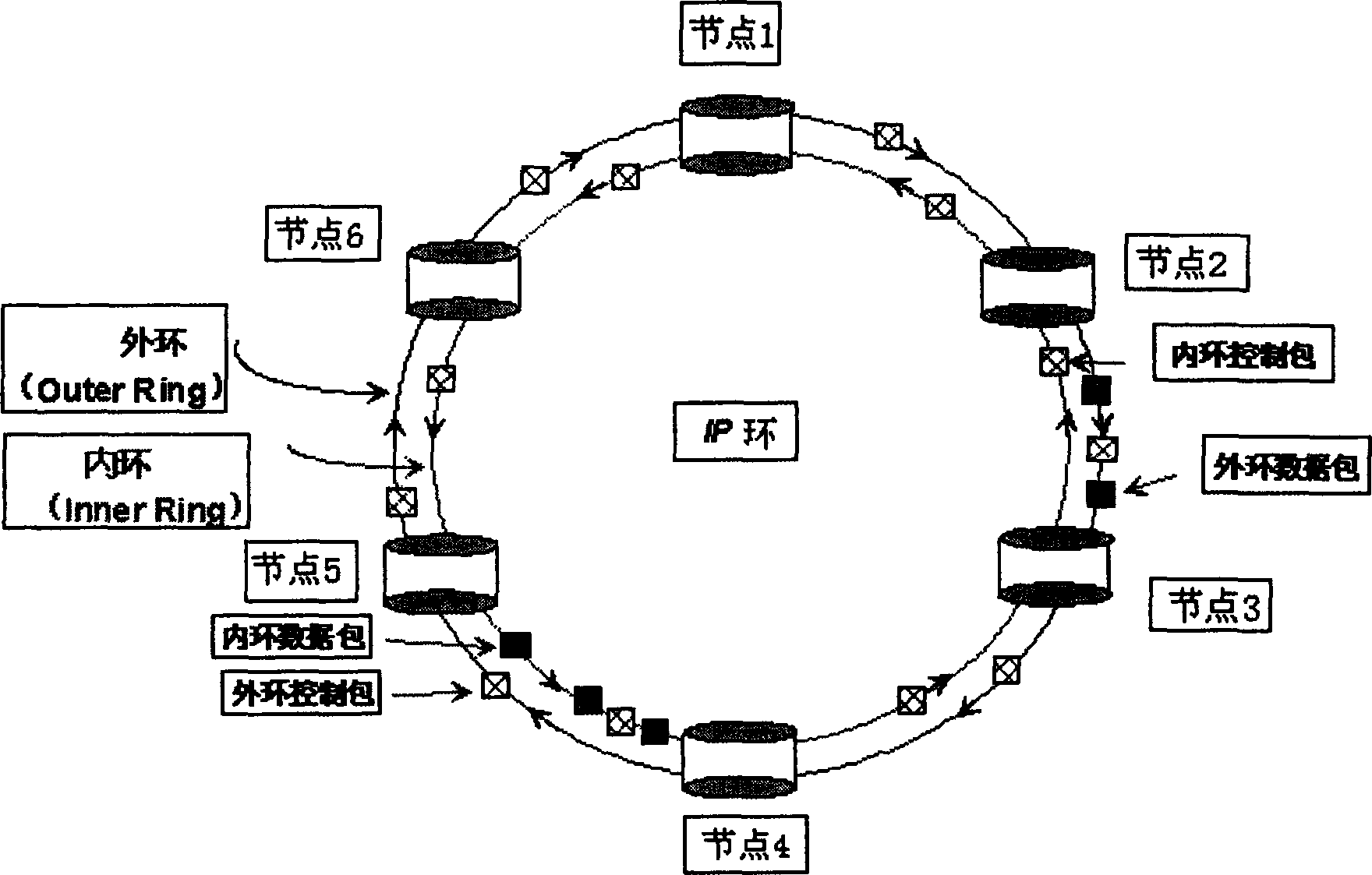
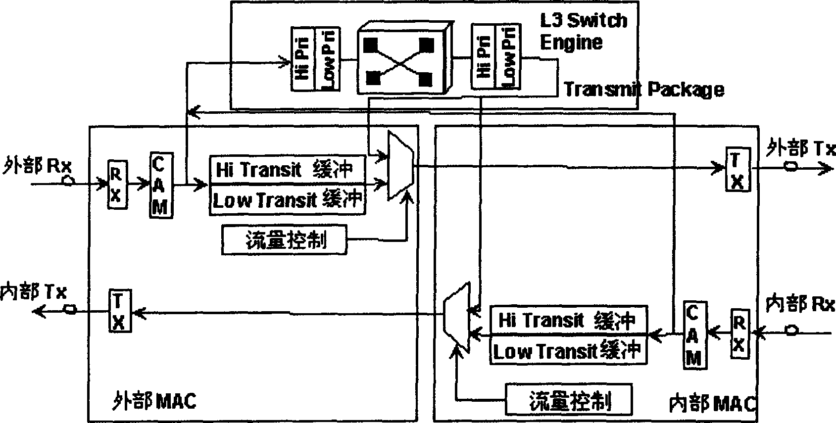
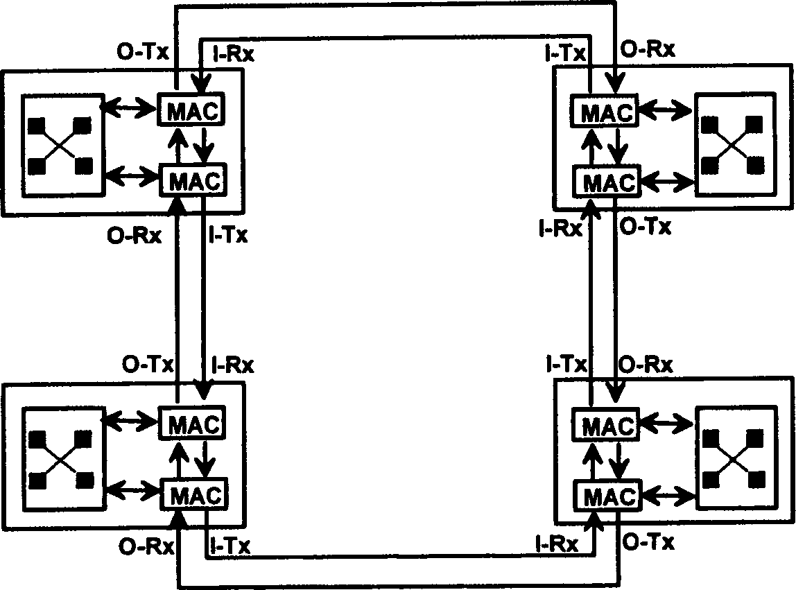
[0062] The present invention will be described in further detail below according to accompanying drawing and embodiment: According to figure 1 , figure 2 , image 3 and Figure 4 , in an IP ring with a double-ring topology structure, access control is performed on each node on the ring, flow control is completed on each node through a certain processing method, and flow control information is transmitted between nodes. IP ring nodes need to be simultaneously Handle the traffic of the inner ring and the outer ring, so an IP ring node is composed of two back-to-back MAC processing chips, which cooperate to process the packets of the inner ring and the outer ring, such as figure 2 As shown, for an IPR node, there are two kinds of input traffic: the traffic received from the upstream node (upstream and downstream according to the packet routing path) and the traffic on the ring of this node, and there are also two kinds of output traffic: from the upstream Sent by a node, the...


PUM


Abstract

An IP distributed bandwidth process method relating to electric communication technology is to carry out a certain access control to every nexus on the IP ring applying dual-ring topological structure, a flow control packet controls data transfer according to congestion nexus information on IP ring and its situated relative position to finish the flow control on each nexus by fair algorithm with weight to transfer flow information mutually, solving the problem of line head blocking

Description

technical field [0001] The invention relates to electric communication technology, in particular to an IP ring distributed bandwidth processing method. Background technique [0002] CISCO proposed DPT technology, namely Dynamic Packet Transport, which is the fourth step in CISCO's optical interconnection strategy. Its core is target node stripping and bandwidth multiplexing, but DPT technology has the feature of Head of line blocking weakness: [0003] DPT's SRP-fa algorithm restricts the "fairness" principle in detail, but does not fully implement bandwidth reuse. When the SRP-fa fairness algorithm restricts the uplink traffic of nodes, it only limits the total traffic. Destination nodes are not considered. Such as figure 1 As shown, assume that node 1, node 2, and node 3 all send data packets from the outer ring to node 4. If node 3 is congested, it will send a flow control packet with flow limit information to node 2 through the inner ring, that is, an announcement pac...

Claims


Application Information

Patent Timeline
07 Jan 2004
Publication
CN1466391A
IPC
H04L12/42; H04L12/801; H04L12/803
CPC
H04L47/122; H04L12/42; H04L47/10
Inventors
张嘉全