Method of drawing routing path drawing using mouse coordinate

A path drawing and coordinate technology, applied in the direction of using manual input to modify/create images, etc., can solve the problems of inefficiency, intelligence and humanization of routing path drawing.

Inactive Publication Date: 2004-08-04
INVENTEC CORP
View PDF0 Cites 4 Cited by
  • Summary
  • Abstract
  • Description
  • Claims
  • Application Information

AI Technical Summary

Problems solved by technology

[0002] In the past, when a layout engineer pulled wires to draw a routing path in a layout job, he usually generated a routing path by specifying the starting point coordinates and the ending point coordinates, and after reconfirmation by the layout engineer , can actually complete the drawing of the routing. However, when such an operation occurs when the routing path is more complicated, the layout engineer must re-specify the starting point coordinates and The coordinates of the end point and the action of confirmation will ca

Method used


Image

  • Method of drawing routing path drawing using mouse coordinate
  • Method of drawing routing path drawing using mouse coordinate
  • Method of drawing routing path drawing using mouse coordinate

Examples


Embodiment Construction

[0031] The present invention will also be described in further detail in conjunction with accompanying drawing:

[0032] The present invention is a method for drawing a wire path by using mouse coordinates. The method of the present invention is established in the computer executable platform software, mainly through the definition and setting of the mouse, in the stage of drawing wires in the layout operation, according to Move and turn the mouse to calculate the routing path to complete the routing path drawing.

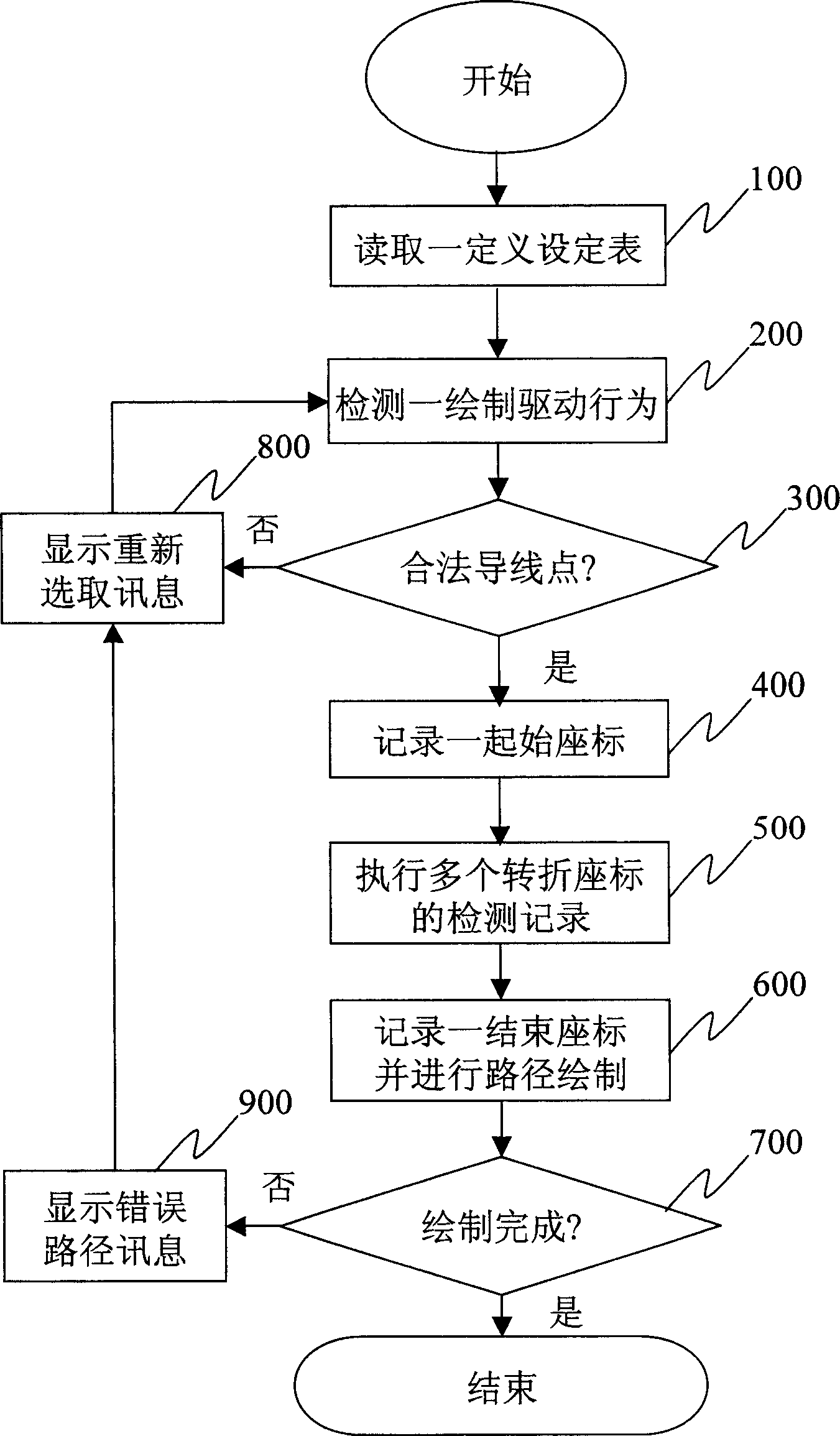
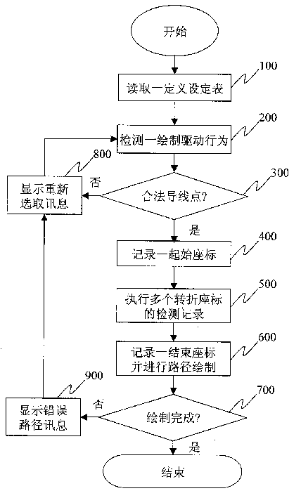
[0033] Figure 1a It is the main operation flow chart of the method for drawing the routing path by using the mouse coordinates provided by the present invention. The following will be explained in conjunction with the part of the drawing:

[0034] At first, the method of the present invention can read definition setting table (step 100), and this table is defined in advance by the user, and wherein at least includes drive termination key setting (comprising: the s...


PUM


Abstract

A method for using the mouse coordinate to draw the routing profile features that the coordinate values at turning points in moving mouse are used to calculate the final routings of wires. Its advantage is high efficiency.

Description

technical field [0001] The present invention relates to a method for drawing a layout operation (layout), in particular to a method for drawing a trace path by using the movement and turning of a mouse in the process of drawing a guide (guide). Background technique [0002] In the past, when a layout engineer pulled wires to draw a routing path in a layout job, he usually generated a routing path by specifying the starting point coordinates and the ending point coordinates, and after reconfirmation by the layout engineer , can actually complete the drawing of the routing. However, when such an operation occurs when the routing path is more complicated, the layout engineer must re-specify the starting point coordinates and The coordinates of the end point and the action of confirmation will cause the layout engineer to often have to repeatedly perform the same designation and confirmation actions, which will be very inefficient in drawing the routing path. [0003] Furthermo...

Claims


Application Information

Patent Timeline
IPC IPC(8): G06T11/80
Inventor 张有权
Owner INVENTEC CORP
Why Eureka
Try Eureka