

Battery pack and method for producing battery pack
A manufacturing method and technology of battery packs, which are applied in the direction of primary batteries to battery packs, battery pack components, battery circuit devices, etc., and can solve problems such as increased battery thickness
- Summary
- Abstract
- Description
- Claims
- Application Information
AI Technical Summary
Problems solved by technology
Method used
Image

Examples
no. 1 example
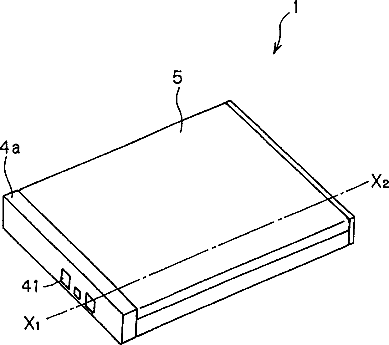
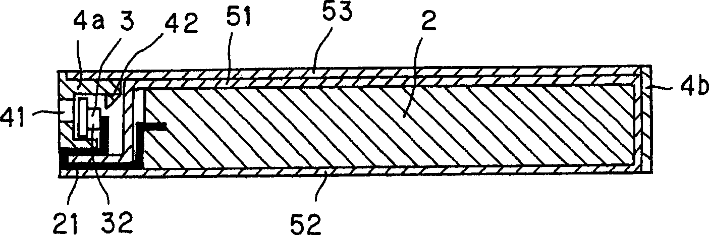
[0067] figure 2 is a perspective view showing an example of a structure of a battery pack to which the present invention is applied. image 3 is along figure 2 Line X in 1 -X 2 cross-sectional view. Figure 4-9 is a schematic diagram explaining a method for manufacturing the battery pack.
[0068] The battery pack 1 includes a battery element 2 , a connection plate 3 , a frame 4 and a case 5 . The battery element 2 is accommodated and sealed in the case 5 and further packaged together with the connecting plate 3 and the frame 4 through the case 5 .
[0069]In the battery element 2, an elongated cathode and an elongated anode are laminated via a polymer electrolyte layer and / or a separator, and the laminate is wound in the longitudinal direction. A cathode terminal 21 and an anode terminal 22 are drawn out from the cathode and the anode, respectively.
[0070] The cathode has a cathode active material layer formed on an elongated cathode current collector and a polymer...
no. 2 example
[0103] Figure 10 is a perspective view showing a structural example of the battery pack 10 used in the present invention. Figure 11 is along Figure 10 Midline X 5 -X 6 cross-sectional view. Figure 12-18 is a diagram for explaining the method of manufacturing the battery pack 10 .
[0104] The battery pack 10 includes a battery element 2, a connecting plate 3, a frame 4 and a case. The battery element 2 is housed and sealed in the casing and further packaged with the connecting plate 3 and the frame 4 through the casing.
[0105] The battery element, connecting plate and frame have basically the same structure as the battery element 2, connecting plate 3 and frame 4 in the first embodiment described above. Therefore, the same reference numerals denote the same elements in the drawings and descriptions thereof are omitted.
[0106] The housing for receiving and enclosing the battery element 2 comprises two housing parts, a first housing part 6 and a second housing par...
no. 3 example
[0134] Now, in the following sections, the Figure 19 and 20 battery pack shown. In this battery pack, the material of the casing is different from that of the battery packs 1 and 10 described above.
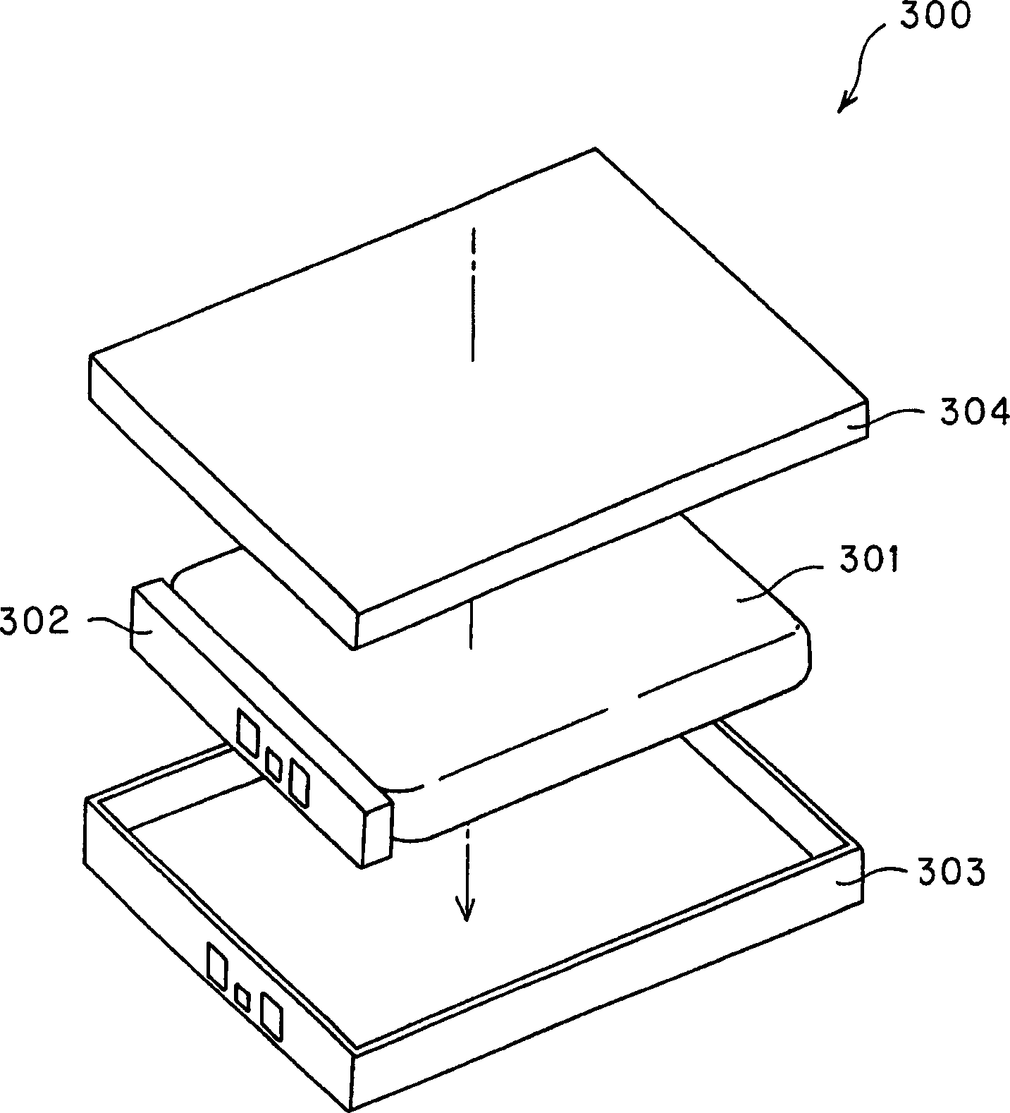
[0135] The battery pack 100 includes a battery element 2, a connecting plate 3, a frame 110 arranged around the battery element 2, a first case 120 for encapsulating the inside of the battery pack, a second case 130 for encapsulating the outside of the battery pack, and a The fixing part 140 of the connecting plate 3 is fixed. In the battery pack 100 , the connection plate 3 and the frame 110 are disposed on the periphery of the battery element 2 enclosed by the first case 120 and the second case 130 so that the frame 110 is connected to the second case 130 . Therefore, the second case 130 also serves as a case material of the battery pack.
[0136] Since the battery element 2 and the connection plate 3 have substantially the same structure as the battery element 2 and the con...
PUM
| Property | Measurement | Unit |
|---|---|---|
| Thickness | aaaaa | aaaaa |
| Vickers hardness | aaaaa | aaaaa |
Abstract
Description
Claims
Application Information