Camera device

A technology for a camera device and camera element, which is used in installation, image communication, instruments, etc., can solve the problems of limited compactness, increased movement, and increased weight, and achieves lightweight, compact, and large travel. Effect

Inactive Publication Date: 2005-12-14
ALPS ALPINE CO LTD
View PDF1 Cites 2 Cited by
  • Summary
  • Abstract
  • Description
  • Claims
  • Application Information

AI Technical Summary

Problems solved by technology

Therefore, not only the mechanism is complicated and the weight increases, but also the compactness is limited
In addition, although it is conceivable to use a piezoelectric element to move the lens instead of being driven by a motor, a certain moving distance is required for the operation of autofocus, and it is difficult to increase the amount of movement when using a piezoelectric element.

Method used


Image

  • Camera device
  • Camera device
  • Camera device

Examples


Embodiment Construction

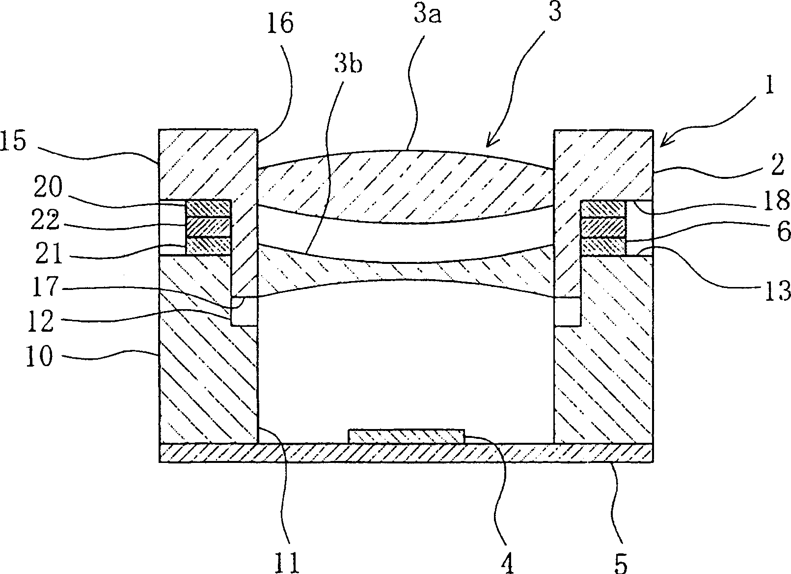
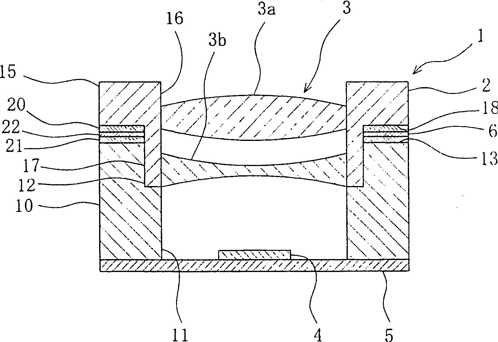
[0028] Embodiments of the present invention will be described in detail below according to the accompanying drawings. figure 1 It is a longitudinal sectional view of the imaging device 1 of this embodiment. As shown in the figure, the imaging device 1 of this embodiment integrally constitutes a lens group 3 housed in a lens barrel 2 and an imaging element 4 that receives light transmitted through the lens group 3, and the lens group 3 faces each other along the optical axis direction. A device that freely moves around the imaging element 4.

[0029] The imaging element 4 is a photoelectric conversion element such as a CCD or a CMOS, and is arranged on a flat substrate 5 . The lens barrel 2 is provided on the substrate 5 so as to surround the imaging element 4 , is formed in a cylindrical shape, and accommodates the lens group 3 inside. The lens group 3 in this embodiment includes a convex lens 3a and a concave lens 3b. However, a single lens may be accommodated in the lens ...


PUM


Abstract

The invention provides an imaging device with simple mechanism, light weight and compactness. In an imaging device (1) provided with a lens (3) accommodated in a lens barrel (2) and an imaging element (4) receiving light passing through the lens (3), the lens barrel (2) includes fixed relative The fixed lens barrel (10) at the position of the imaging element (4) and the movable lens barrel (15) that is arranged so that the end face and the fixed lens barrel (10) are opposite to each other and accommodates the lens (3) are opposite to each other. Each end face of the fixed lens barrel (10) and the movable lens barrel (15) is connected by a telescopic drive element (6), thereby making the lens (3) accommodated in the movable lens barrel (15) relative to the The imaging element (4) moves freely.

Description

technical field [0001] The present invention relates to an imaging device in which a lens and an imaging element are integrated, and more particularly to an imaging device in which the relative position of the lens and the imaging element is changed to automatically focus. Background technique [0002] Conventionally, there is known a camera in which a lens is freely movable relative to an imaging element in the direction of the optical axis for autofocusing. As such an imaging device, there is a device in which a lens is moved in parallel by a rotation operation of a motor or a screw or the like. Patent Document 1 shows a conventional imaging device. [0003] [Patent Document 1] Japanese Patent Application Laid-Open No. 5-80242 [0004] However, in conventional imaging devices, a motor is used to drive the lens, and therefore a mechanism for converting the rotational motion of the motor into linear motion is required. Therefore, not only is the mechanism complicated and ...

Claims


Application Information

Patent Timeline
Patent Type & Authority Applications(China)
IPC IPC(8): G02B7/02G02B7/04G02B7/08H04N5/225
CPCG02B7/09G02B7/22G02B9/12G02B5/003G03B30/00
Inventor 林政道山下龙麿吉行仁志松尾荣树
Owner ALPS ALPINE CO LTD
Why Eureka
Try Eureka