Method for producing high efficiency energy saving fan vane using fin structure section bar

A fan impeller, high-efficiency and energy-saving technology, applied in the field of fan impeller processing, can solve the problems that affect the performance of the fan, the performance difference of the prototype, and the twist angle value is difficult to form a continuous and uniform change, so as to achieve the effect of ensuring the stability of the control

Inactive Publication Date: 2006-03-22
韩军
View PDF2 Cites 11 Cited by
  • Summary
  • Abstract
  • Description
  • Claims
  • Application Information

AI Technical Summary

Problems solved by technology

This method has the following deficiencies: (1) affected by the operating conditions of the blower fan, the forms of the blades are various, so when processing, they will correspond to profiles of various cross-section forms, and there is no clear processing standard in the whole processing process in this invention , not only is it difficult to form large-scale, standardized, and serialized production, but it will also seriously affect the performance of the fan, causing a large difference between product performance and design results and prototype performance, and it is difficult to meet the design requirements; (2) the twist angle processing method There are deficiencies, one of the methods disclosed in the document: "clamp both ends of the blade with a fixture, let the two fixtures rotate relative to each other, and give a torsion moment to the blade blank", the blade processed by this method, from the blade root to the blade top The torsion angle of the fan blade is uniform and consistent, which cannot meet the aerodynami...

Method used


Image

  • Method for producing high efficiency energy saving fan vane using fin structure section bar
  • Method for producing high efficiency energy saving fan vane using fin structure section bar
  • Method for producing high efficiency energy saving fan vane using fin structure section bar

Examples


Embodiment 1

[0060] Example 1: Blade profile

[0061] The blade profile used in the present invention has been published in the patent document submitted by the applicant (patent number: 200420052872.4; invention name: hollow airfoil fan blade profile with central shaft hole).

[0062] The typical cross-sectional design structure of its profiles can be divided into the following categories:

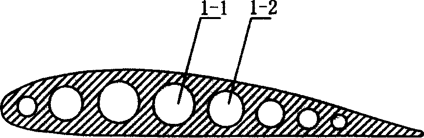
[0063] 1. The cross-sectional structure of the formed blade that does not need to be filled when twisting, as shown in Figures 1, 2, 5, and 6;

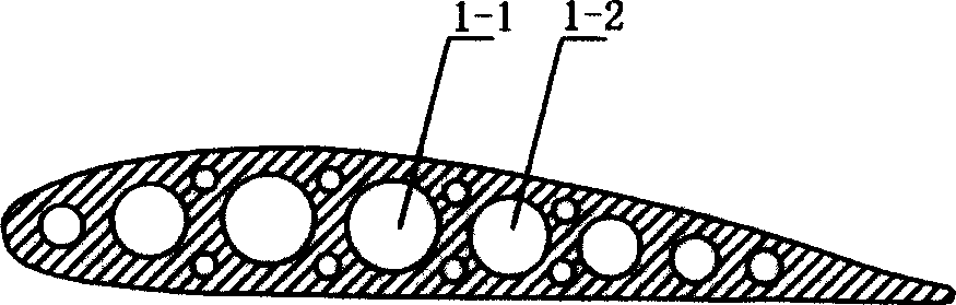
[0064] 2. The cross-sectional structure of the formed blade that must be filled during twisting, as shown in Figures 3 and 4;

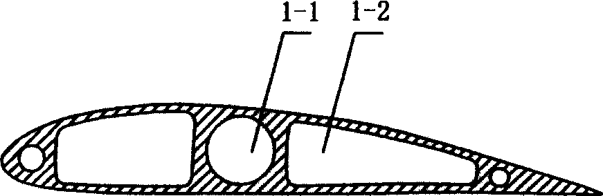
[0065] 3. The cross-sectional structure of blades that can be modified, as shown in Figures 5 and 6;

[0066] 4. Combined plug-in structure airfoil section structure, as shown in Figure 7.

Embodiment 2

[0067] Embodiment 2: the manufacture of the fan impeller that does not need to be filled when the blade is twisted (the blade section structure is shown in accompanying drawings 1, 2, 5, and 6)

[0068] step:

[0069] (1) Design the structure of the airfoil blade according to the requirements of the performance index of the fan for different purposes and the design requirements of the blade mentioned above, and then make the aluminum alloy airfoil blade profile by extrusion method, and the hardness of the profile is controlled between 70-90 degrees between;

[0070] According to the size requirements of the fan blades, cut the profile blanking;

[0071] (2) Use the torsion equipment to process the profile.

[0072] (3) Use cutting equipment to cut and process the root of the profile;

[0073] (4) Setting of impeller connector

[0074] Select a suitable type of stud as the impeller connector, and fix one end of the stud in the positioning hole at the root of the blade;

[...

Embodiment 3

[0080] Embodiment 3: the manufacture of the fan impeller that must be filled when the blade is twisted (the blade cross-sectional structure is as shown in accompanying drawing 3, 4)

[0081] step:

[0082] (1) According to the performance requirements of fans for different purposes and the design requirements of the blades mentioned above, the structure of the airfoil blade is designed, and then the aluminum alloy airfoil blade profile is made by extrusion, and the hardness of the profile is controlled between 70-90 degrees ;

[0083] According to the size requirements of the fan blades, cut the profile blanking;

[0084] (2) Use fine sand or other materials to fill the profile square hole;

[0085] (3) Use the torsion equipment to process the profile;

[0086] (4) Remove powdery filling materials;

[0087] (5) Utilize the cutting equipment to cut and process the blade root;

[0088] (6) Setting of impeller connector

[0089] According to the wind pressure on the blade, ...


PUM

PropertyMeasurementUnit
Hardnessaaaaaaaaaa

Abstract

The present invention relates to fan vane wheel making technology. The process of making efficient energy saving fan vane wheel with fin structure section bar includes twisting vane section bar, machining the contact curved surface between the vane root and the hub, setting vane wheel connecting part, vane surface modification, connecting the vane root and the hub and vane wheel surface protecting treatment. The said process can produce low noise energy saving vane wheel, and can meet the personalized design requirement and realize mass production of vane in high production efficiency and high product quality. The present invention may be used widely in manufacture of different kinds of fan.

Description

technical field [0001] The invention relates to a processing method for fan impellers, more precisely, a method for manufacturing high-efficiency and energy-saving fan impellers by using airfoil structural profiles. Background technique [0002] The performance of the fan impeller depends to a large extent on the shape of the fan impeller blades. In the prior art, the usual processing methods for airfoil fan blades are molding, casting, mold milling, and manual modification. The impeller is heavy. , high energy consumption, large-scale production is difficult, and quality is not easy to guarantee. At present, there is no processing method with a clear processing standard that can truly adapt to mass production of airfoil fan blades. Publication No. CN 1406708A discloses a method for processing the blades of axial flow fans. It is to extrude the aluminum alloy profiles of equal cross-section of the airfoil on the extruder, and then clamp the two end...

Claims


Application Information

Patent Timeline
IPC IPC(8): B23P15/04
Inventor 韩军
Owner 韩军
Why Eureka
Try Eureka