Oil smoke-expelling utensil capable of forming spirally- ascending air current

A spiral rising and oil fume exhaust technology, which is applied in the direction of oil fume removal, household appliances, household heating, etc., can solve the problems of large motor noise, high wind pressure, and overflow, and achieve the effect of reducing load, significant effect, and noise reduction

Inactive Publication Date: 2006-09-06
吕才树
View PDF0 Cites 9 Cited by
  • Summary
  • Abstract
  • Description
  • Claims
  • Application Information

AI Technical Summary

Problems solved by technology

In this way, there are various problems in terms of work efficiency, function and other side effects. For example, the inhaled air volume is not large, the air pressure is too high, the noise of the motor is large, the oil fume cannot be collected well, and there is an overflow phenomenon.

Method used


Image

  • Oil smoke-expelling utensil capable of forming spirally- ascending air current
  • Oil smoke-expelling utensil capable of forming spirally- ascending air current
  • Oil smoke-expelling utensil capable of forming spirally- ascending air current

Examples


example 1

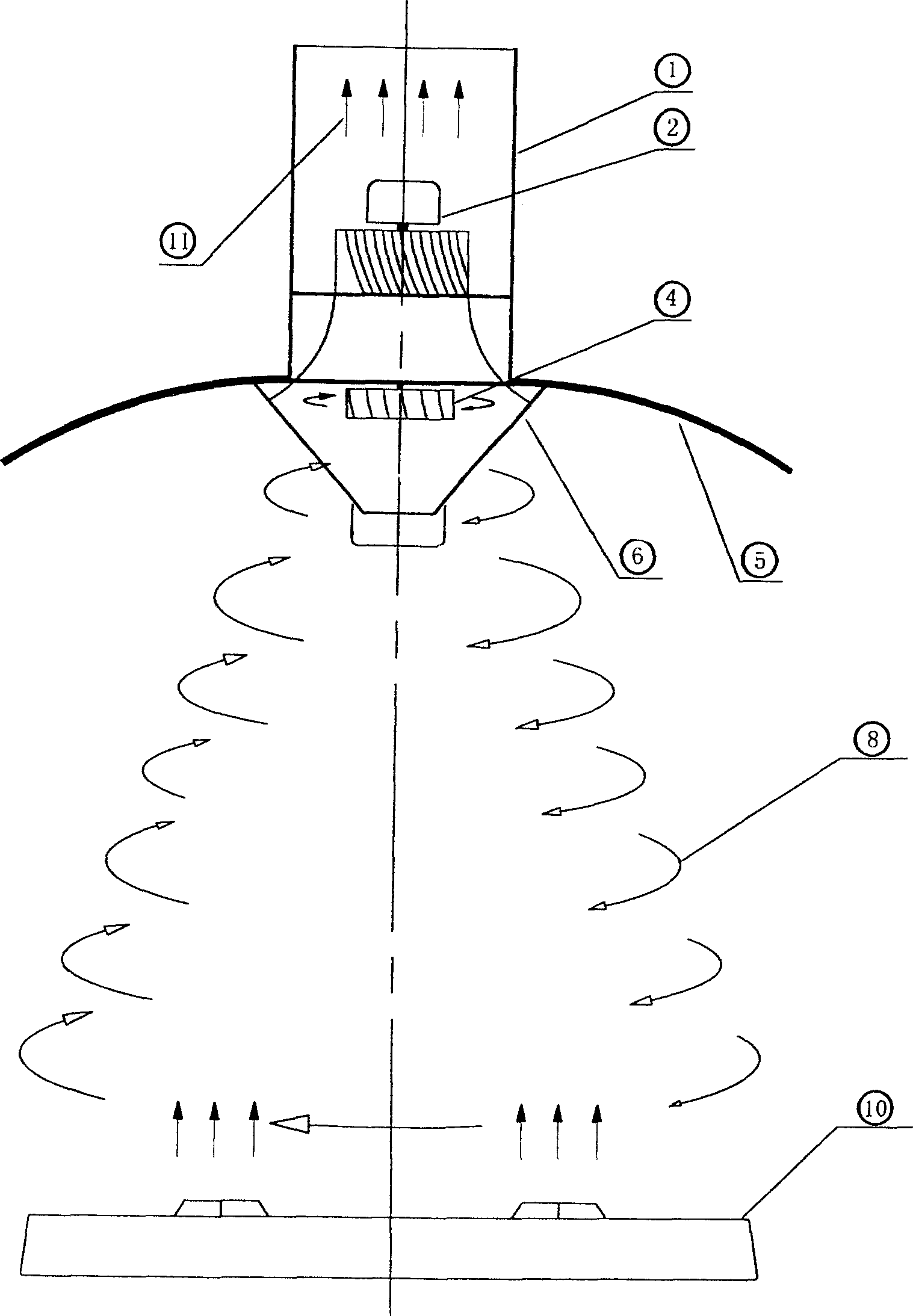
[0016] Example 1: If figure 1 As shown, under the action of the motor 2, the oil fume appliance is at the lower air inlet of the air duct 1 of the oil fume exhaust appliance. A side power vane 4 is installed, and the side power vane 4 starts to rotate through the airflow sucked by the motor 2 to generate the effect of side wind force, thus realizing the purpose of side power. Then because the kitchen stove 10 produces a large amount of water vapor and oil fume 9 when the fuel burns and cooks, it continuously flows upwards. Therefore, there are two conditions for locally forming the tornado effect, and the original uplift force and side power can be added to form a spiral upward airflow that approximates the tornado effect.

example 2

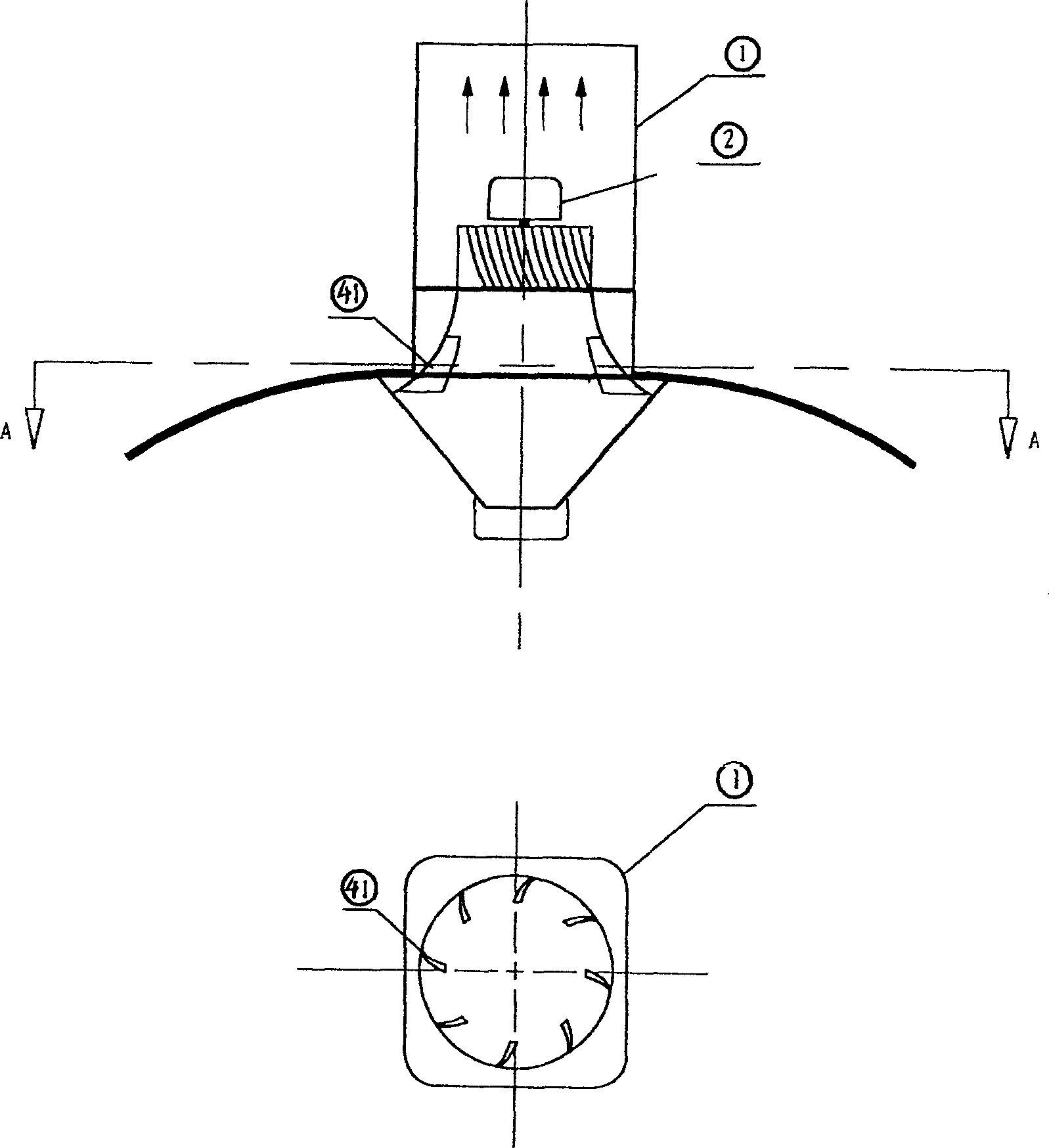
[0017] Example 2: If figure 2 As shown, the top is a schematic diagram of the structure, and the bottom is the A-A diagram. To realize the spiral upward airflow, two necessary conditions must be met, one is the upward force of the traction airflow. The 2nd, side power (biasing force), traction airflow lifting force all possesses at present. Then, by spot-welding the iron sheet 41 similar to the turbine vane on the periphery between the lower air inlet of the air duct 1 of the oil fume exhaust device and the fume collecting hood, the wind force of the inhaled airflow when flowing is decomposed and becomes a lateral force , so the purpose of side power can also be achieved.

example 3

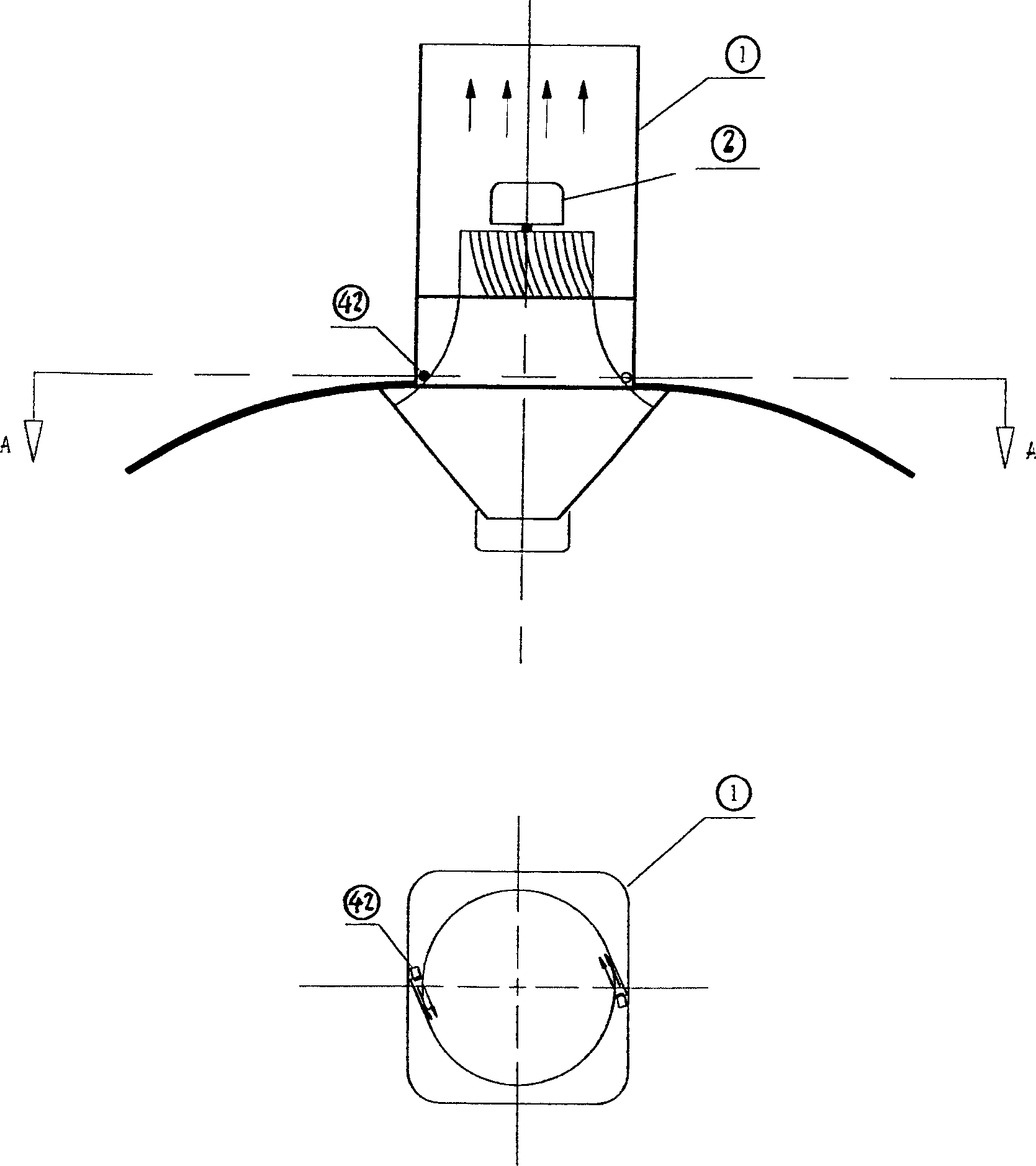
[0018] Example 3: If image 3 As shown, the top is a schematic diagram of the structure, and the bottom is the A-A diagram. To realize the spiral upward airflow, two necessary conditions must be met: the one is the lifting force of the traction airflow, and the other is the side power (biasing force). At present, the lifting force of the traction airflow has been possessed, so then at the lower air inlet of the oil fume exhaust appliance air duct 1, two (or more than two) side air intake motors 42 are symmetrically arranged on the air duct wall, and its air duct is along the main The tangential direction arrangement of the air duct circumference can also realize side power. In addition, other conditions are possessed equally, so the spiral updraft of approximate tornado effect can also be realized.


PUM


Abstract

The invention relates to an oil smoke exhaust device for forming cyclone ascending airflow, which comprises a smoke collecting cover with a wind channel above and a oil collecting cover downward; the wind channel has a bracket with a motor as whorl motor; the wind inlet of said wind channel has a whorl generator which is the side-power wind blade at the middle of wind inlet of wind channel or the side-power wind blade near the wind inlet and the smoke collecting cover, or the side wind inlet motor between the wind inlet and the smoke collecting cover. The invention can fix the oil smoke and avoid overflow and realize oil smoke discharge.

Description

technical field [0001] The present invention relates to an appliance for removing oily fume in the kitchen, in particular to a kind of locally generated spiral upward airflow, thereby gathering and stabilizing the oily fume generated in the local space, and the spiral upward airflow has a strong upward impact force And the hollow feature, so as to reduce the resistance of the oil collecting cover and the oil cup, and completely remove the oil fume. Background technique [0002] Most of the cooking fume removal appliances in the kitchen appliances on the market are direct-suction or side-suction, and the structural design of the air duct is relatively simple. In this way, there are various problems in its work efficiency, functions and other side effects. For example, the air volume sucked is not large, the wind pressure is too high, the noise of the motor is large, the oil fume cannot be collected well, and there is an overflow phenomenon. Contents of the invention [000...

Claims


Application Information

Patent Timeline
Patent Type & Authority Applications(China)
IPC IPC(8): F24C15/20
Inventor 吕才树
Owner 吕才树
Why Eureka
Try Eureka