Energy recovery latch circuit with set and reset function

A latch circuit and energy recovery technology, applied in logic circuits, electrical components, pulse technology, etc., can solve the problems of no setting/resetting of output signals, complex circuit structure, and limiting the application range of adiabatic circuits.

Inactive Publication Date: 2006-10-11
FUDAN UNIV
View PDF0 Cites 9 Cited by
  • Summary
  • Abstract
  • Description
  • Claims
  • Application Information

AI Technical Summary

Problems solved by technology

The former can achieve zero power consumption in theory, but reversible logic must be used in the circuit to complete the function of the circuit. This kind of circuit structure is complex and requires a large number of pulse power sources, which is very difficult to realize; while the latter is relatively It is said that the structure of the circuit is relatively simple, there is no limitation of reversible logic, the pulse power used in the circuit is relatively small, and it is relatively easy to apply
However, the charge recovery efficiency of this circuit has a theoretical limit. When the circuit completes the logic function, it must consume a certain proportion of energy, at least Es=(1 / 2)·C g ·V th 2 , this part of the power dissipation is the non-adiabatic power dissipation
[0012] Due to the potential huge practical value of semi-adiabatic circuits, research on semi-adiabatic circuits has been very active internationally in recent years. Not only have many new types of adiabatic circuit structures emerged, but these latches have an obvious shortcoming: the output The signal does not have a set / reset control, that is, these adiabatic latches do not have a set / reset function
Therefore, the application range of adiabatic circuits in the field of sequential logic circuit design is greatly limited.

Method used


Image

  • Energy recovery latch circuit with set and reset function
  • Energy recovery latch circuit with set and reset function
  • Energy recovery latch circuit with set and reset function

Examples


Embodiment Construction

[0035] The present invention is further illustrated below by an embodiment.

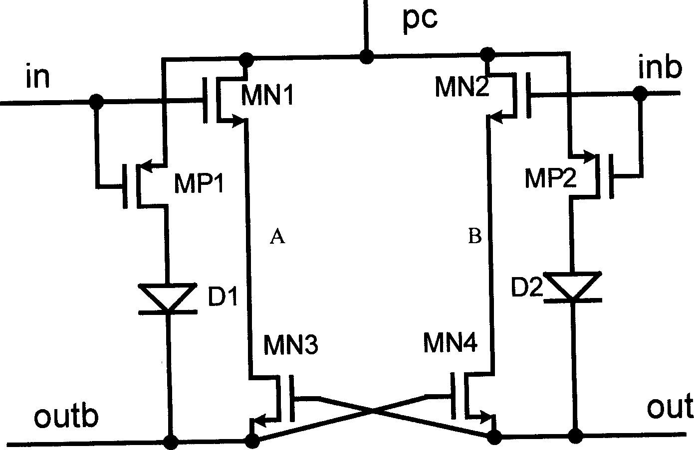
[0036] refer to Figure 5 As shown, it is a latch circuit structure with a set / reset function based on a 2n-2n2p2d complementary cross-coupled energy recovery circuit structure, including:

[0037] Two sets of transmission gate structures (MP1 and MN1, MP2 and MN2) connected in series to control the on / off of the power clock (PC signal) by the set / reset signal; the gates of the PMOS transistors are respectively connected to the set / reset signal S, R, the source of MP1 is connected to the power clock (PC signal), the drain of MP1 is connected to the source of MP2, and the drain of MP2 is connected to node C; the gates of the NMOS transistors are respectively connected to the set / reset complementary signals Sb, Rb, the drain of MN1 is connected to the power clock (PC signal), the source of MN1 is connected to the drain of MN2, and the source of MN2 is connected to the C node;

[0038] A pair of PMOS ...


PUM


Abstract

The related energy-recovery latch circuit with set and reset function comprises: the gating devices MN1, MN2, MP1 and MP2 with power clock controlled by set/reset signal; a couple of unilateral conductive devices D1 and D2 to charge the differential output nodes; a couple of PMOS tubes MP3 and MP4 to control the pre-charge branch by input signal and its complementary signal D and Db for latch; a couple of PMOS tubes MP5 and MP6 to control the pre-charge branch by set/reset complementary signal Sb and Rb for set/reset; a couple of NMOS tubes MN3 and MN4 for logical operation, a couple of NMOS tubes MN5 and MN6 for set/reset, and a couple of NMOS tubes MN7 and MN8 for cross coupling output. This invention just needs very low power consumption for logic sequence control.

Description

technical field [0001] The invention belongs to the technical field of low-power integrated circuit design, and in particular relates to an energy recovery latch circuit with a set / reset function, which is used in a sequential logic circuit of a semi-insulated circuit. Background technique [0002] Adiabatic Circuit Technique (Adiabatic Circuit Technique), also known as charge recovery technology, is a new low-power technology that has emerged in the past ten years. Because the power consumption of circuits designed with this technology can be significantly reduced (theoretically, it can be reduced is zero), now it has become a hot spot in low power consumption research and an important research direction in the field of low power consumption integrated circuit technology. [0003] Traditional latches are composed of CMOS circuits. We know that the dynamic power consumption of CMOS circuits is an important component of the overall power consumption of the circuit, and it som...

Claims


Application Information

Patent Timeline
Patent Type & Authority Applications(China)
IPC IPC(8): H03K19/0944H03K19/00
Inventor 何艳田佳音廖友春王俊宇闵昊
Owner FUDAN UNIV
Why Eureka
Try Eureka