Uni-index variable angle ultrasonic phased array probe

One index point, single technology for use in ultrasound probes

Inactive Publication Date: 2007-03-21
GENERAL ELECTRIC CO
View PDF1 Cites 14 Cited by
  • Summary
  • Abstract
  • Description
  • Claims
  • Application Information

AI Technical Summary

Problems solved by technology

Thus, echoes and defects such as those coming from the back side may be more easily identified

Method used


Image

  • Uni-index variable angle ultrasonic phased array probe
  • Uni-index variable angle ultrasonic phased array probe
  • Uni-index variable angle ultrasonic phased array probe

Examples


Embodiment Construction

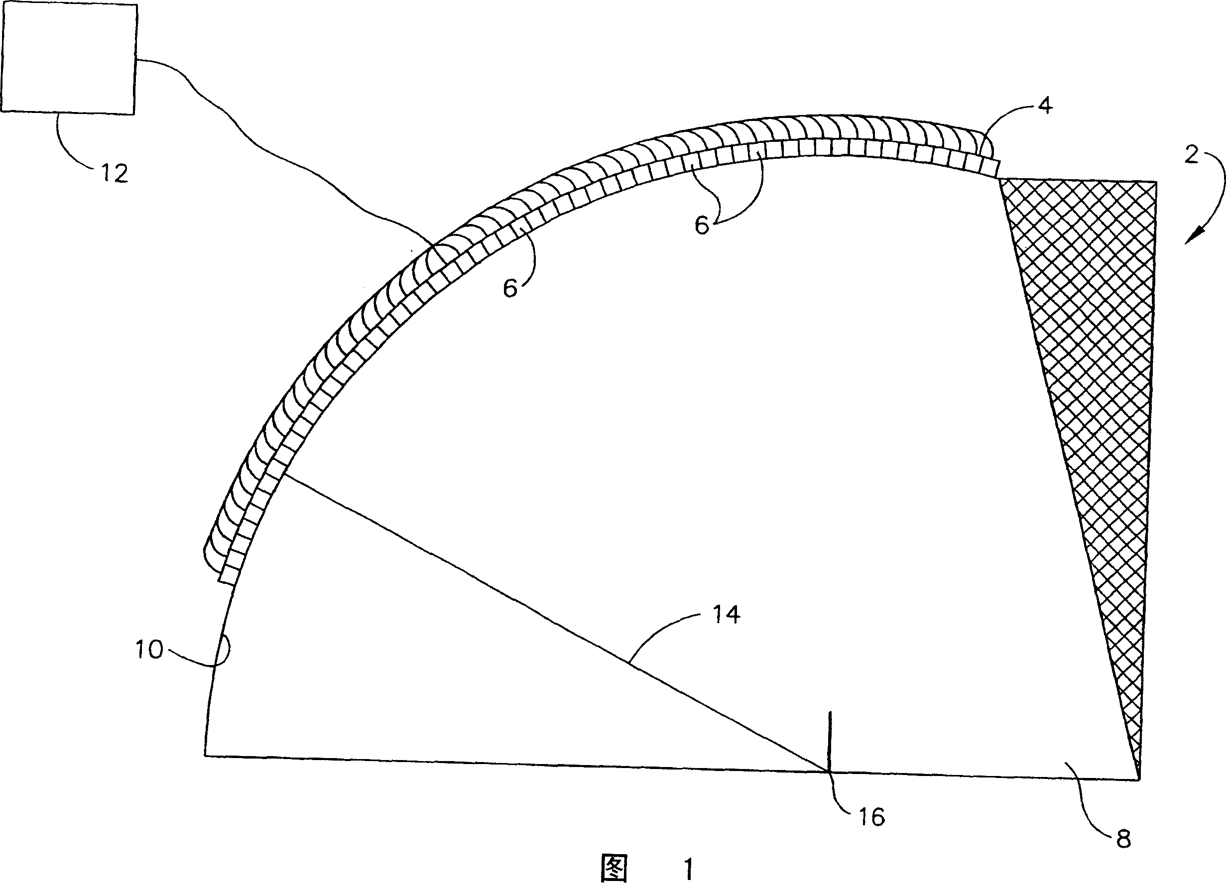
[0026] The ultrasonic probe of the present invention utilizes a retarder having a convex outer surface with a constant radius. The probe is depicted in Figure 1. The probe 2 includes an array element 6 comprising a plurality of 1-n The transducer array 4, where n can be any integer. The array element 6 is mounted on the convex outer surface 10 of the retarder 8 . The retarder can be any solid material as known in the art. Typically, retarders are constructed of Plexiglas, polystyrene, or other polymeric materials. Each transducer array element 6 in the transducer array 4 is connected to a generator 12 which provides an electrical signal which is converted by the element into mechanical sound waves of a preselected frequency as is known in the art. Acoustic waves generated by each transducer array element of transducer array elements 6 are substantially along the x The position of the radius to the center 16 of the radius 14, also referred to as the origin, is transmitted ...


PUM


Abstract

An ultrasonic probe (2) used for inspecting a workpiece (44) comprising a delay body (8) and a transducer array (4) having a plurality of transducer elements (6) mounted on the delay body (8). The plurality of transducer elements (6) of the transducer array (4) are mounted on the curved outer surface of the delay body (8). The transducer elements (6) in the array of elements are equidistant from a center of the radius of curvature (14) of the delay body (8), so that sound waves simultaneously generated by two or more of the transducer elements (6) arrive at the center of the radius, also referred to as the origin point (16), at the same time. The reflected sound passing through the index point received by a transducer in the array (4) is not subject to a time delay resulting from the geometry of the delay body (8).

Description

technical field [0001] The present invention relates to an ultrasonic probe in the form of a transducer array, and more particularly to an ultrasonic probe having a probe body having a geometry such that the transducers in the transducer array are within a distance from the origin in the probe body are equidistant, so sound waves produced simultaneously by two or more transducers in the array arrive at the origin at the same time. Background technique [0002] Ultrasonic probes are used to inspect workpieces in industrial applications. Such inspections have been performed by the contact method, where the probe is brought into intimate contact with the workpiece, but coupled to the workpiece using a couplant such as glycerin or oil, or by non-contact or immersion methods, where a column of water is positioned between the workpiece and the transducer between. [0003] The probe includes a delay body, and at least one transducer mounted on the delay body. The at least one tr...

Claims


Application Information

Patent Timeline
Patent Type & Authority Applications(China)
IPC IPC(8): G01N29/24G01N29/22
CPCG01N2291/2632G10K11/02G01N2291/0422G01N29/262G01N2291/044G01N2291/0421G01N29/2468G01N29/0618G01N2291/106
Inventor T·J·卡罗迪斯基
Owner GENERAL ELECTRIC CO
Why Eureka
Try Eureka