Engine cam shaft cover with oil sump

A camshaft cover and engine technology, applied in the lubrication of valve accessories, etc., can solve the problems of increasing the specific pressure bearing strength of the bearing surface, affecting the formation of oil film, increasing the difficulty of the arrangement of the mechanism of the compact engine, etc., achieving good lubrication effect, The effect of simple structure

Inactive Publication Date: 2007-04-11
CHONGQING CHANGAN AUTOMOBILE CO LTD
View PDF0 Cites 6 Cited by
  • Summary
  • Abstract
  • Description
  • Claims
  • Application Information

AI Technical Summary

Problems solved by technology

[0003] In the existing gas distribution mechanism of the engine, the oil supply passage for lubricating the camshaft is usually located at the camshaft bearing. Firstly, the specific pressure of the bearing surface is increased and the stren

Method used


Image

  • Engine cam shaft cover with oil sump
  • Engine cam shaft cover with oil sump
  • Engine cam shaft cover with oil sump

Examples


Embodiment Construction

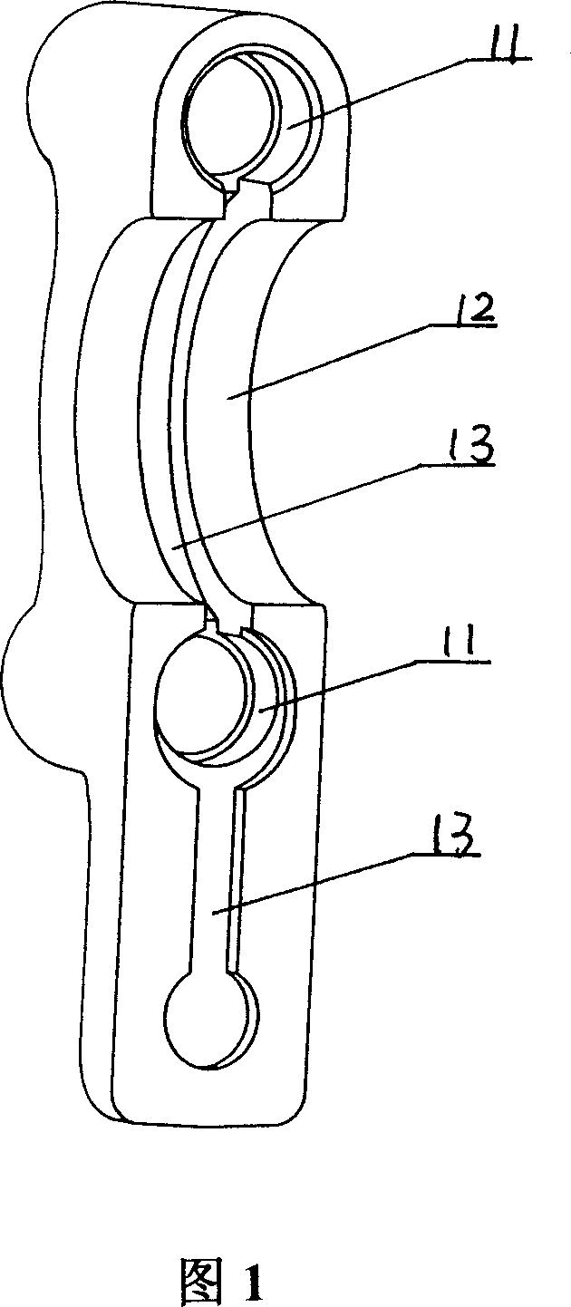
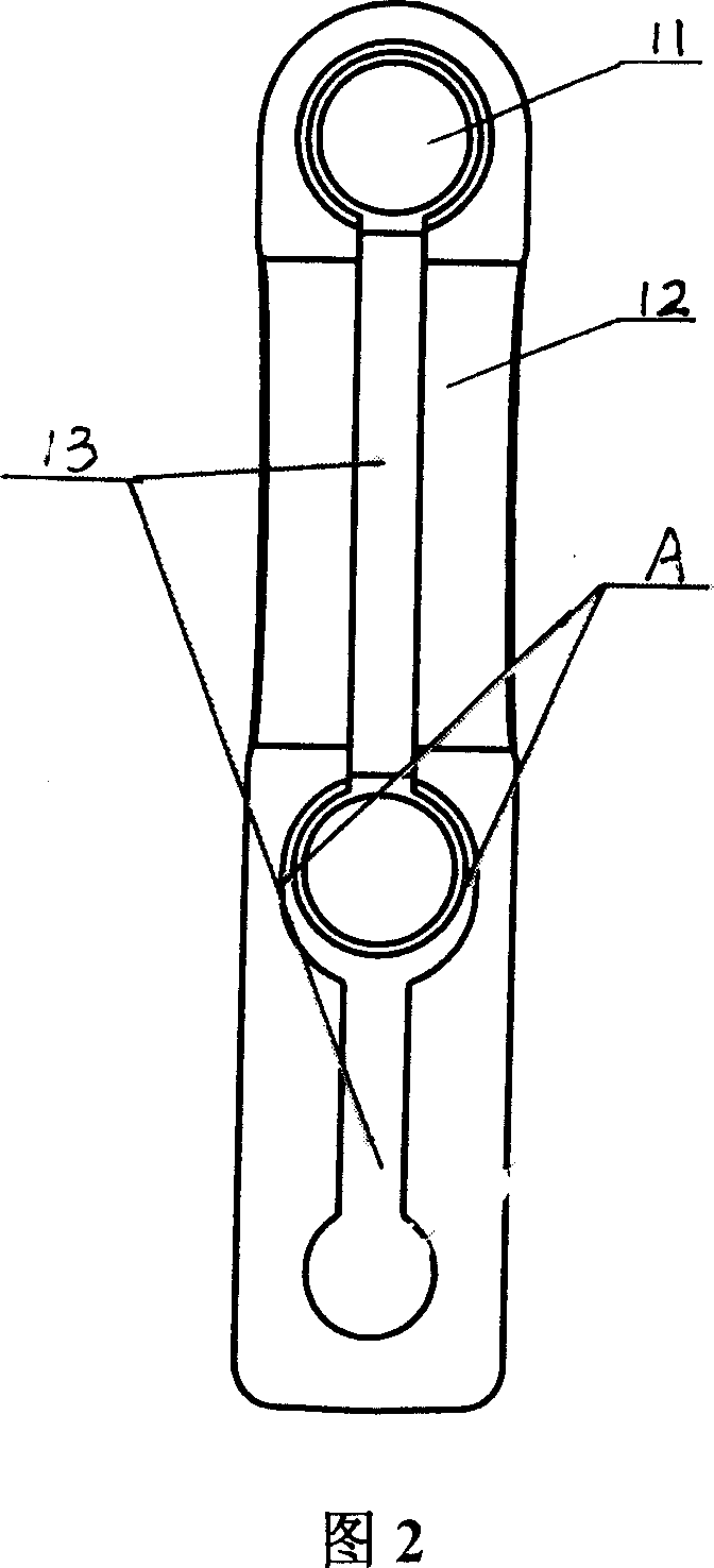
[0012] Referring to Fig. 1 and Fig. 2, the two ends of the camshaft cover are bolt holes 11 fixed to the cylinder head of the engine, and the middle is a curved surface 12 adapted to the camshaft. Oil groove 13 is made on top, in order to access lubricating oil from cylinder head conveniently, one end of camshaft cover is extended, and oil groove 13 just passes the bolt hole 11 of this end along the joint surface from the extended end of camshaft cover, then leads to the other side along joint surface. Bolt holes 11 at one end. In order to ensure the smooth flow of the oil passage, when the oil groove passes through the bolt hole at the extension end, an eccentric structure A is adopted, as shown in Figure 2.

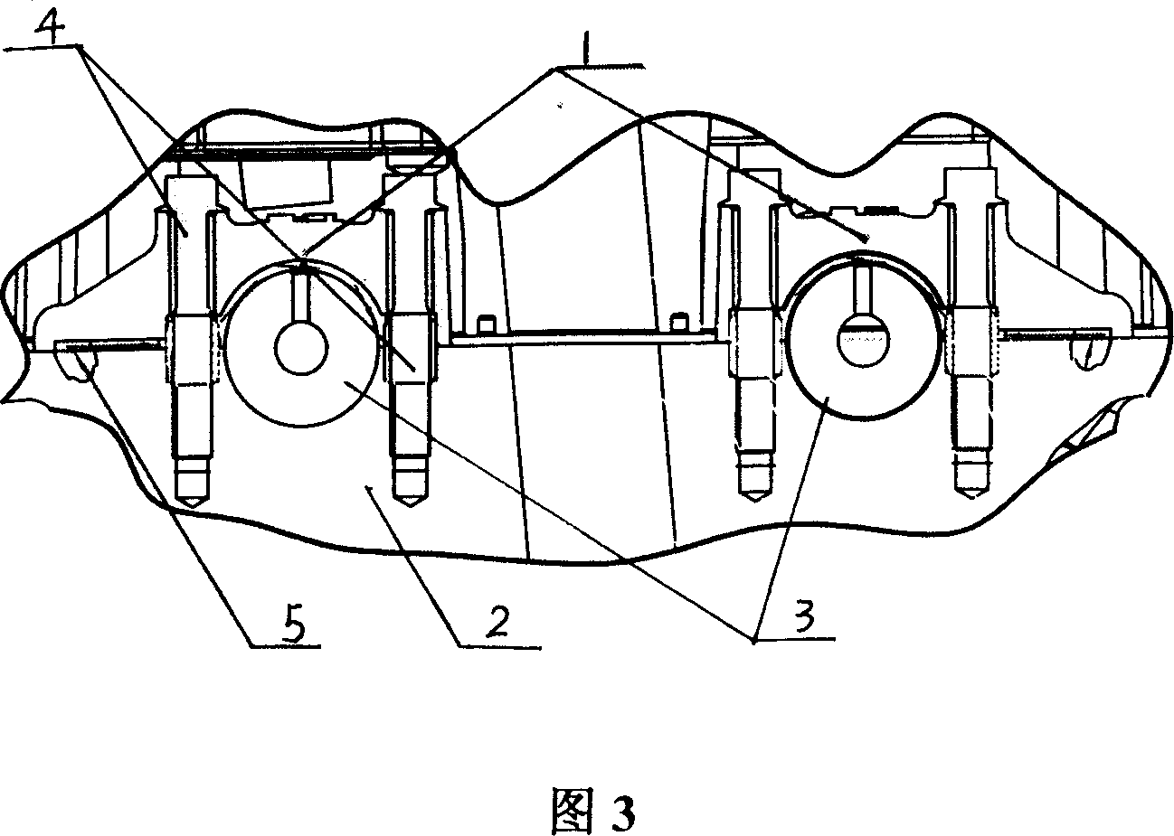
[0013] It can be seen from Figure 3 of the assembly relationship between the camshaft cover 1, the cylinder head 2 and the camshaft 3 that the camshaft cover 1 is fixed to the cylinder head 2 through bolts 4, one on the left and one on the left, and the oil groove 13 is...


PUM


Abstract

The present invention proposes one kind of cam shaft cover with oil sump for engine. The cam shaft cover has screw holes for screw fixing onto the cylinder cover of the engine, curved surface in the middle part for fitting the cam shaft, and one prolonged end with oil sump communicated to the main oil path in the cylinder cover. The cam shaft cover makes the lubricant oil flowing through the curved surface between two screw holes well contact with the cam shaft, so as to increase the lubricating area and raise the lubricating effect. The present invention has the advantages of simple structure and good lubricating effect.

Description

Technical field: [0001] The invention belongs to the lubricating technology of an engine valve mechanism. Background technique: [0002] In the lubrication system of the engine, the oil pump is used to generate a certain pressure of the lubricating oil, and it is continuously sent to the friction surfaces for lubrication. This method is suitable for the friction surface with heavy load, high speed and no moving parts exposed on the friction surface. Such as main bearings, connecting rod bearings, camshaft bearings and valve rocker shafts. [0003] In the existing gas distribution mechanism of the engine, the oil supply passage for lubricating the camshaft is usually located at the camshaft bearing. Firstly, the specific pressure of the bearing surface is increased and the strength of the bearing is reduced, and the oil film at this position is also affected. Formation is not conducive to achieving the best effect of lubrication; secondly, it increases the difficulty of the...

Claims


Application Information

Patent Timeline
IPC IPC(8): F01M9/10
Inventor 祝勇成卫国余训
Owner CHONGQING CHANGAN AUTOMOBILE CO LTD
Why Eureka
Try Eureka