Waste heat boiler

A waste heat boiler and waste gas flow technology, which is applied to water heaters, fluid heaters, heat exchange equipment, etc., can solve the problems of hot spots on the exhaust chamber wall, shortened maintenance cycles, and shortened life of waste heat boilers, so as to avoid corrosion, Improve the service life, improve the function and the effect of life

Inactive Publication Date: 2007-06-20
ARVOS GMBH
View PDF1 Cites 8 Cited by
  • Summary
  • Abstract
  • Description
  • Claims
  • Application Information

AI Technical Summary

Problems solved by technology

In the control plugs currently used, there is the disadvantage that the exhaust gas flowing out of the open bypass line outlet forms a strong strand (Ströhne), which leads to the risk of hot spots on th

Method used


Image

  • Waste heat boiler
  • Waste heat boiler
  • Waste heat boiler

Examples


Embodiment Construction

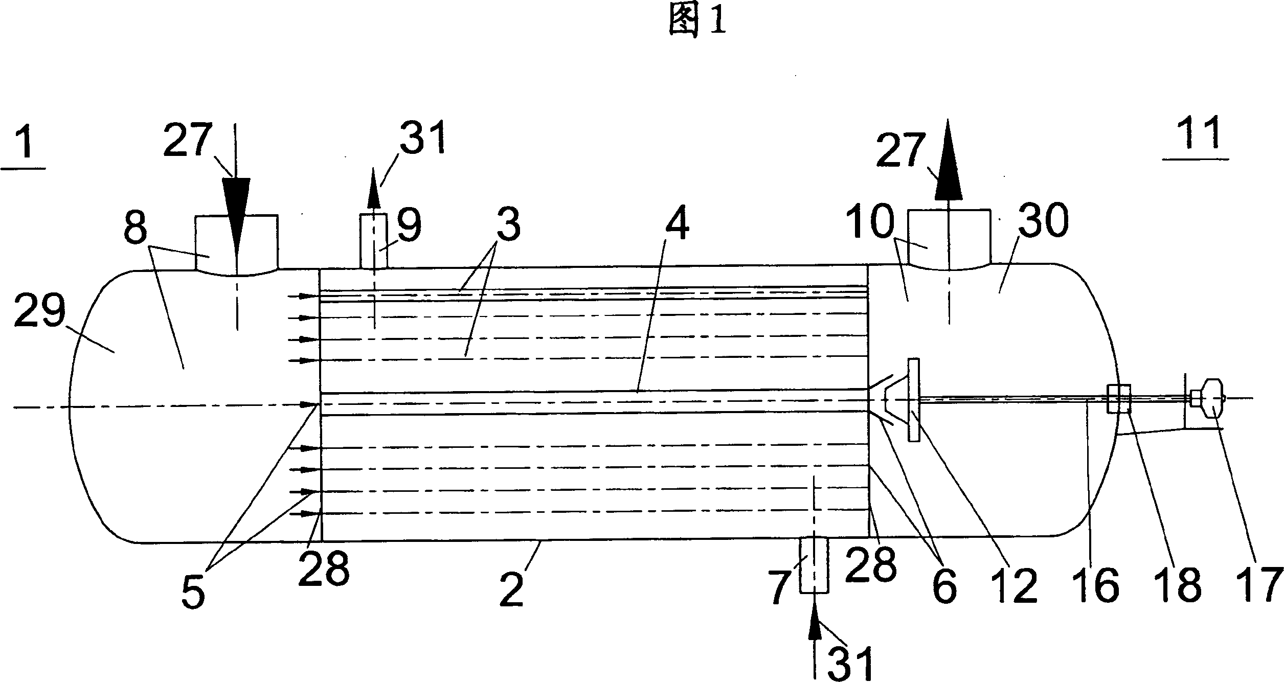
[0024] FIG. 1 schematically shows a waste heat boiler 1 in longitudinal section. Such waste heat boilers are required for different chemical and petrochemical processes. The waste heat boiler 1 has a casing 2 which encloses a large number of heat transfer tubes 3 and a centrally arranged bypass tube 4, wherein the tubes 3, 4 are surrounded at their inlet and outlet ends 5, 6 by tube end plates 28 such that A cavity for conducting a cooling medium 31 for cooling the high-temperature exhaust gas flow 27 is formed in the housing 2 and the end plate 28 . The bypass pipe 4, which preferably has a larger diameter than the heat transfer pipe 3, can be partially or completely insulated over its length, so that the sometimes very high temperature exhaust gas 27 on the bypass pipe 4 cannot be conveyed too much to the cooling medium 31 The heat flows through the waste heat boiler 1. Viewed along the flow direction of the exhaust gas 27, that is, parallel to the longitudinal axis of the...


PUM


Abstract

A waste heat boiler includes an axial bypass pipe and multiple heat transfer pipes disposed within a cylindrical jacket. A hot exhaust gas stream transported between inlet and outlet ends of the heat transfer pipes is cooled by a coolant. A control system controls gas passage velocity and quantity of the exhaust gas stream through the bypass pipe whereby the exhaust gas stream exhaust temperature is maintained within a predetermined temperature range. The control system includes a stopper disposed at the outlet end of the bypass pipe and has a head plate extending into the outlet end of the bypass pipe. The stopper is axially displaceable from a closed position, where an outer surface of the stopper head plate contacts an inner surface of the bypass pipe outlet end. The gas passage formed between the inner surface of the bypass pipe outlet end and the outer surface of the stopper head plate has a cross-section that increases as the stopper is axially displaced from the closed position.

Description

technical field [0001] The invention relates to a waste heat boiler comprising a plurality of heat transfer tubes and a centrally located bypass tube in a cylindrical housing, each having an inlet port and an outlet port and including a regulating device for exhausting the waste heat boiler The temperature is kept within a certain temperature range. The present invention particularly relates to a waste heat boiler. In order to control the exhaust temperature of the waste heat boiler, its regulating device is installed on the outlet end of the bypass pipe. Background technique [0002] For many chemical and petrochemical processes, waste heat boilers require the flow of different gaseous and / or liquid media through the tubes and shell faces (channel side). Here, the high-temperature exhaust gas from the working process is usually fed to heat transfer tubes and bypass tubes which are arranged as tube bundles in the shell of the waste heat boiler. When the high-temperature ex...

Claims


Application Information

Patent Timeline
IPC IPC(8): F24H1/40
CPCF28F27/02F28D7/16F22B1/1838F22B35/001F22B1/1884F28F2250/06F22B35/007
Inventor J·耶克勒H·奥尔曼K·罗滕皮勒
Owner ARVOS GMBH
Why Eureka
Try Eureka