Steering wheel

a steering wheel and wheel technology, applied in the direction of tyre parts, light guides, transportation and packaging, etc., can solve the problems of increasing costs and power consumption, and achieve the effect of reducing costs and power consumption

Active Publication Date: 2019-04-02
TOYODA GOSEI CO LTD
View PDF46 Cites 2 Cited by
  • Summary
  • Abstract
  • Description
  • Claims
  • Application Information

AI Technical Summary

Benefits of technology

[0004]It is an object of the present invention to provide a steering wheel that reduces costs and power consumption.

Problems solved by technology

This increases costs and power consumption.

Method used


Image

  • Steering wheel
  • Steering wheel
  • Steering wheel

Examples


Embodiment Construction

[0024]One embodiment of a steering wheel for a vehicle will now be described with reference to FIGS. 1 to 14. To facilitate understanding, features may be exaggerated in FIGS. 1 to 14 and elements may have not necessarily been drawn to scale.

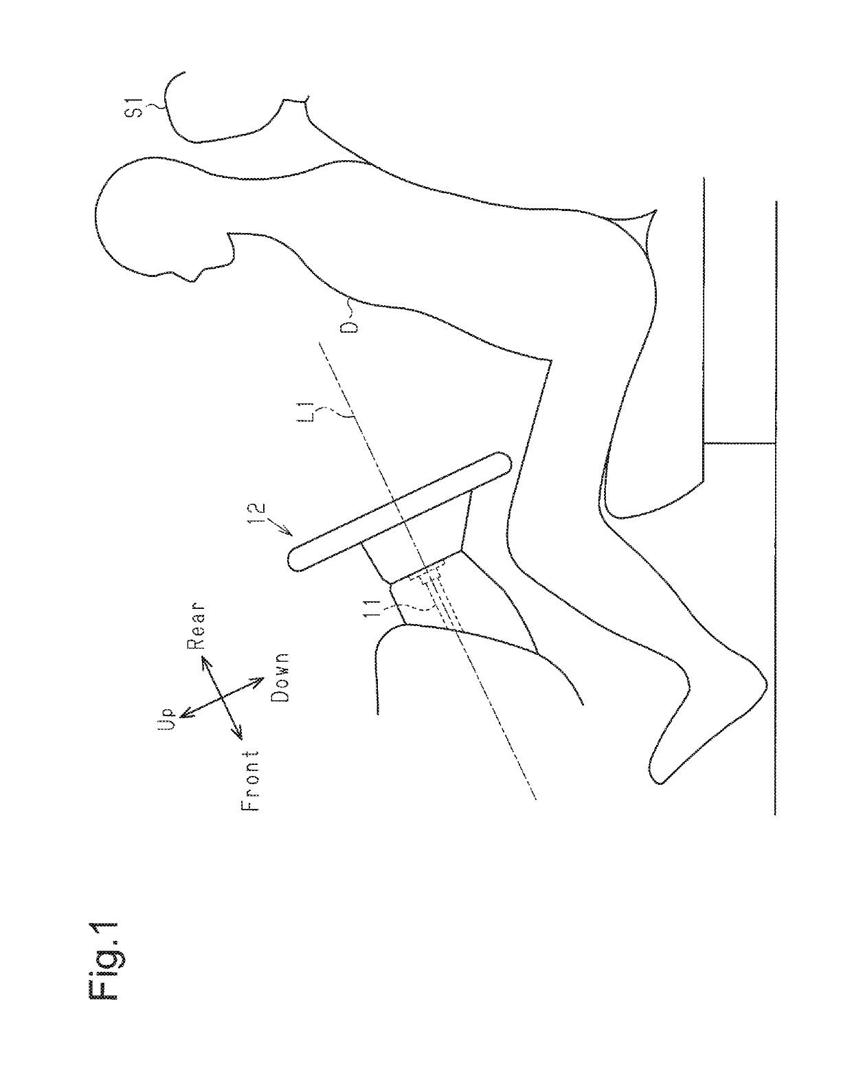
[0025]As shown in FIG. 1, a steering shaft 11 rotated about an axis L1 is arranged at the front side (left side as viewed in FIG. 1) of a driver seat S1 in a vehicle. The steering shaft 11 is inclined in the vehicle so that the steering shaft 11 is higher as the steering shaft 11 becomes closer to the driver seat S1 (right side as viewed in FIG. 1). A steering wheel 12 is coupled to and rotated integrally with a rear end of the steering shaft 11.

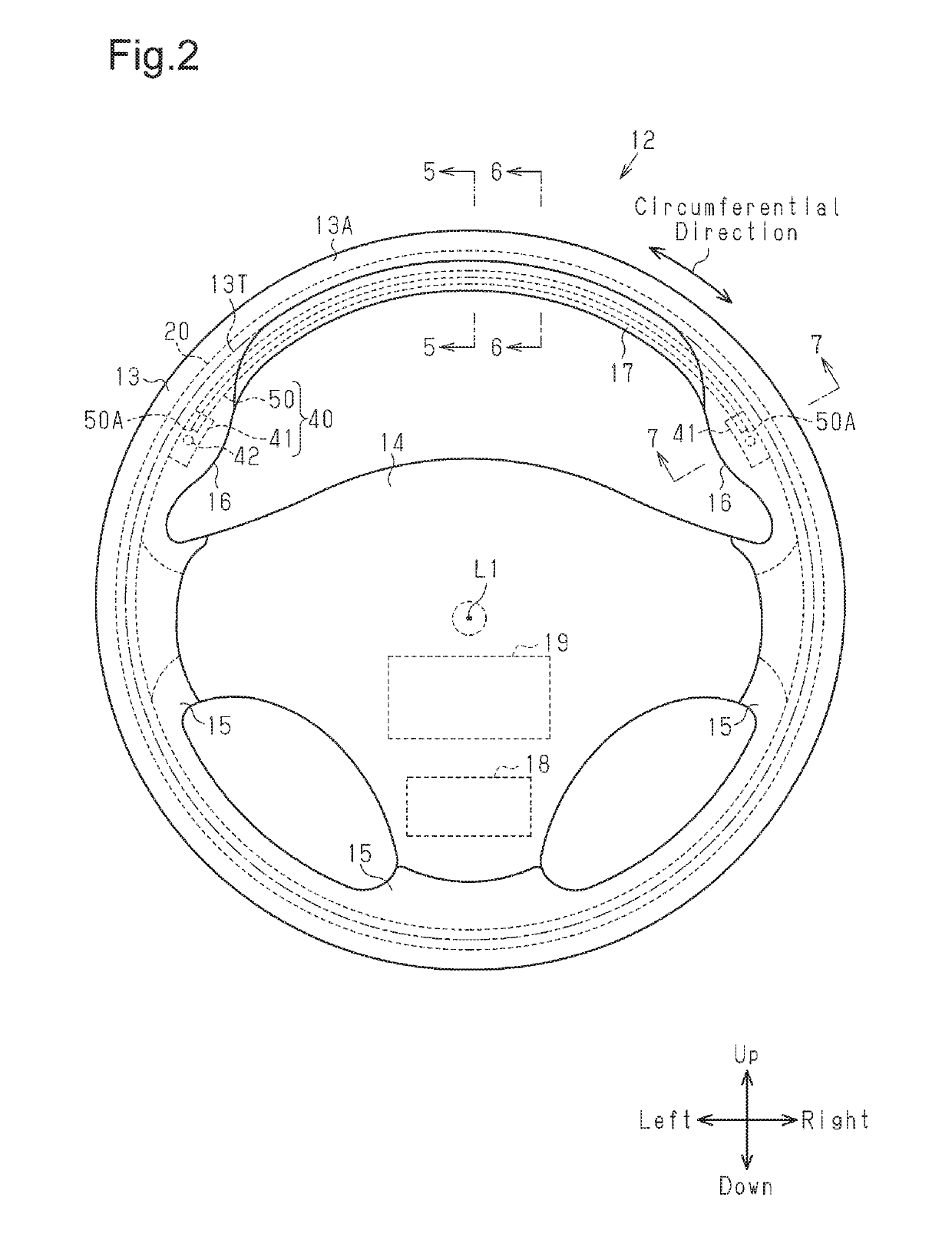
[0026]In this specification, the direction extending along the axis L1 of the steering shaft 11 is referred to as the “front-to-rear direction” of the steering wheel 12, and among the directions extending along a surface orthogonal to the axis L1, the direction in which the steering wheel 12 extends is r...


PUM


Abstract

A steering wheel includes an indicator. The indicator includes a light source that emits light and a light guide. The light guide includes an outer surface and an end opposing the light source. The light emitted from the light source enters the end of the light guide, and some of the light is emitted from the outer surface.

Description

BACKGROUND OF THE INVENTION[0001]The present invention relates to a steering wheel.[0002]A steering wheel known in the art includes a ring provided with an indicator (refer to, for example, Japanese Laid-Open Patent Publication No. 2014-69671). In such a steering wheel, the ring includes a groove, and a light emitting diode serving as the indicator is arranged in the groove. The light emitting diode indicates, for example, information related to autonomous driving, the vehicle speed, the engine speed, the vehicle interior temperature, the radio frequency, and the selected transmission gear.[0003]In the steering wheel, a large number of light emitting diodes are arranged in the groove that is formed in a circumferential direction of the ring. This increases costs and power consumption.SUMMARY OF THE INVENTION[0004]It is an object of the present invention to provide a steering wheel that reduces costs and power consumption.[0005]To achieve the above object, a steering wheel according ...

Claims


Application Information

Patent Timeline
Patent Type & Authority Patents(United States)
IPC IPC(8): B60Q1/00B60Q3/64B60Q3/80B60Q3/283B60C23/00G08B5/22B60Q1/34B60Q1/54B62D1/04B60Q9/00B62D1/06
CPCB60Q3/283B60Q3/64B60Q3/80B62D1/06B60Q9/008B62D1/046B60Q9/002B60K35/00B60K2370/33B60K2370/332B60K2370/336B60K2370/338B60K2370/782
Inventor ASAKAWA, RENGENAGATA, ATSUSHIHIBINO, YASUSHITAKEDA, SHINICHI
Owner TOYODA GOSEI CO LTD
Why Eureka
Try Eureka