Unlock instant, AI-driven research and patent intelligence for your innovation.

Control apparatus for performing focus detection, image capturing apparatus, control method, and non-transitory computer-readable storage medium

a control apparatus and focus detection technology, applied in the field of image capture apparatuses, can solve the problem of limited correlation calculation time for one image, and achieve the effect of stably performing high-speed and high-accuracy focus adjustmen

Active Publication Date: 2019-06-18
CANON KK
View PDF19 Cites 3 Cited by
  • Summary
  • Abstract
  • Description
  • Claims
  • Application Information

AI Technical Summary

Benefits of technology

The present patent is about a device (control apparatus, image capturing apparatus, control method, and computer-readable storage medium) that can quickly and accurately adjust the focus. This invention provides a better solution for users who need to capture images of high-speed or high-accuracy.

Problems solved by technology

Furthermore, in the imaging-plane phase difference AF, since the correlation calculation needs to be performed in synchronization with the imaging signal, a permissible correlation calculation time for one image is limited.

Method used


Image

  • Control apparatus for performing focus detection, image capturing apparatus, control method, and non-transitory computer-readable storage medium
  • Control apparatus for performing focus detection, image capturing apparatus, control method, and non-transitory computer-readable storage medium
  • Control apparatus for performing focus detection, image capturing apparatus, control method, and non-transitory computer-readable storage medium

Examples


first embodiment

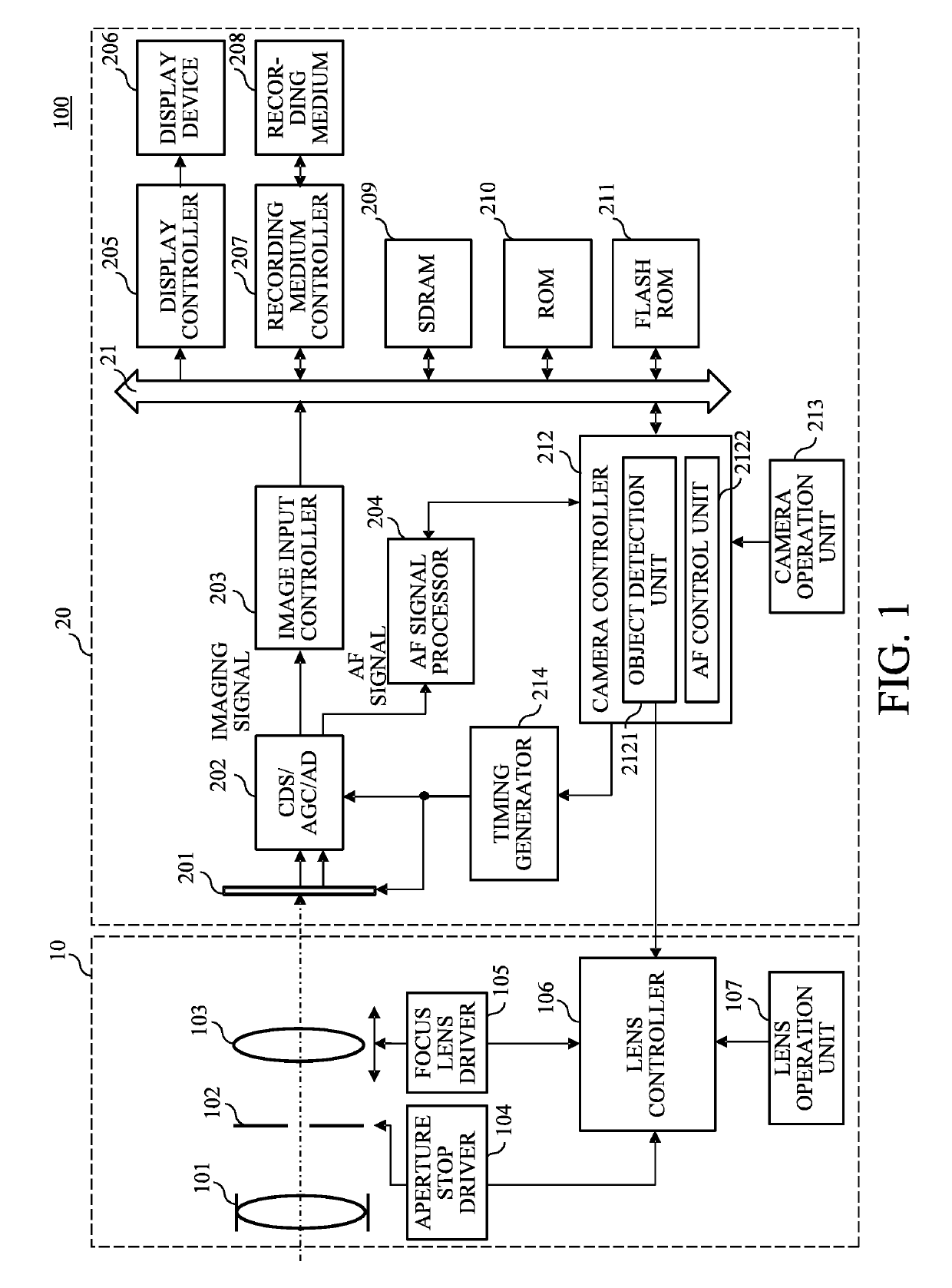
[0026]First, referring to FIG. 1, a configuration of an image capturing apparatus in a first embodiment of the present invention will be described. FIG. 1 is a block diagram of an image capturing apparatus 100 (lens interchangeable camera system) in this embodiment. The image capturing apparatus 100 includes a camera body 20 (image capturing apparatus body) and a lens unit 10 (interchangeable lens) detachably attached to the camera body 20. A lens controller 106 that manages control of an entire operation of the lens unit 10 and a camera controller 212 that manages control of an entire operation of the image capturing apparatus 100 (camera system) including the lens unit 10 are communicated to each other via a terminal (not illustrated) provided in a lens mount. This embodiment can also be applied to an image capturing apparatus where a lens unit and a camera body are integrated.

[0027]First, the configuration of the lens unit 10 will be described. A fixed lens 101, an aperture stop ...

second embodiment

[0080]Next, a second embodiment of the present invention will be described. This embodiment is different from the first embodiment in the setting of the detection property (step S403 in FIG. 4). That is, the camera controller 212 sets a plurality of focus detection areas, and as the type of the focus adjustment operation, it changes the detection property depending on the type of the focus detection area as a target of setting of the detection property (i.e., whether the focus detection area is the main area). Since other configurations and operations are the same as those of the first embodiment, description thereof will be omitted.

[0081]FIG. 11 is a flowchart of illustrating setting of the detection property (step S403) in this embodiment. Each step of FIG. 11 is mainly performed by the camera controller 212.

[0082]First, at step S1101, the camera controller 212 determines whether the focus detection area as a target of setting the detection property is the main area (i.e., main fo...

third embodiment

[0086]Next, a third embodiment of the present invention will be described. This embodiment is different from the first embodiment in that a second defocus threshold value is set (changed) depending on at least one of an image capturing condition and a state of an AF image signal.

[0087]Referring to FIG. 12, the focus adjustment operation (focus control) in this embodiment will be described. FIG. 12 is a flowchart of illustrating a procedure of the focus adjustment operation in this embodiment. FIG. 12 differs from FIG. 4 only in that step S420 is inserted between step S408 and step S409 in FIG. 4, and accordingly the descriptions of steps other than step S420 are omitted.

[0088]When it is determined at step S408 that the reliability is equal to or higher than a first reliability threshold value, the flow proceeds to step S420. At step S420, the AF control unit 2122 sets a second defocus threshold. Commonly, the second defocus threshold value is determined based on the calculated defoc...


PUM


Abstract

A control apparatus (204, 212) includes a calculator (204) that calculates a defocus amount based on a first signal and a second signal that correspond to light beams passing through different pupil regions of an image capturing optical system (101, 102, 103) from each other, and a focus adjuster (212) that performs focus adjusting operation based on the defocus amount, and the focus adjuster is configured to change a detection property of the first signal and the second signal depending on a type of the focus adjusting operation.

Description

BACKGROUND OF THE INVENTIONField of the Invention[0001]The present invention relates to an image capturing apparatus that performs focus detection.Description of the Related Art[0002]In recent years, as a phase difference AF (imaging-plane phase difference AF) using an image sensor, a method of acquiring a captured image using pixels of the image sensor and performing focus detection is proposed. According to the imaging-plane phase difference AF, object detection and focus adjustment can be performed based on signals obtained from the same image sensor, and as a result it is possible to perform high-speed and high-accuracy focus adjustment.[0003]Japanese Patent Laid-open No. 2001-083407 discloses a configuration where a plurality of photodiodes corresponding to one microlens are provided and each photodiode receives light of different pupil planes of an imaging lens. With such a configuration, it is possible to compare outputs of the two photodiodes to perform the imaging-plane pha...

Claims


Application Information

Patent Timeline
Patent Type & Authority Patents(United States)
IPC IPC(8): H04N5/232
CPCH04N5/23212H04N5/23245H04N23/672H04N23/667
Inventor KAWANISHI, ATSUYAMATSUI, YOHEIIWASAKI, NAOKI
Owner CANON KK