Conductor unit

a technology of conductors and components, applied in the direction of coupling contact members, coupling device connections, cores/yokes, etc., can solve the problem that the friction between the conductor and the core may damage the coating of the conductor

Active Publication Date: 2019-07-16
YAZAKI CORP +1
View PDF19 Cites 4 Cited by
  • Summary
  • Abstract
  • Description
  • Claims
  • Application Information

AI Technical Summary

Benefits of technology

[0005]It is an object of the present invention to provide a conductor unit that can protect a coating of a conductor from being damaged.

Problems solved by technology

If a conductor is movable relative to the core, a friction between the conductor and the core may damage a coating of the conductor during conveyance and / or in an assembly process.

Method used


Image

  • Conductor unit
  • Conductor unit
  • Conductor unit

Examples


first embodiment

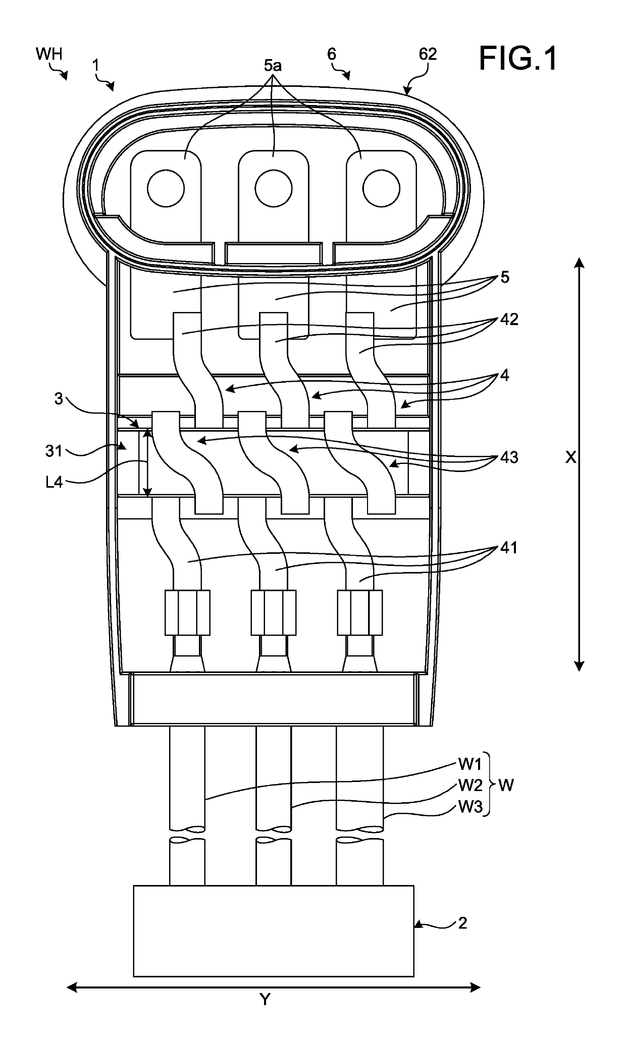
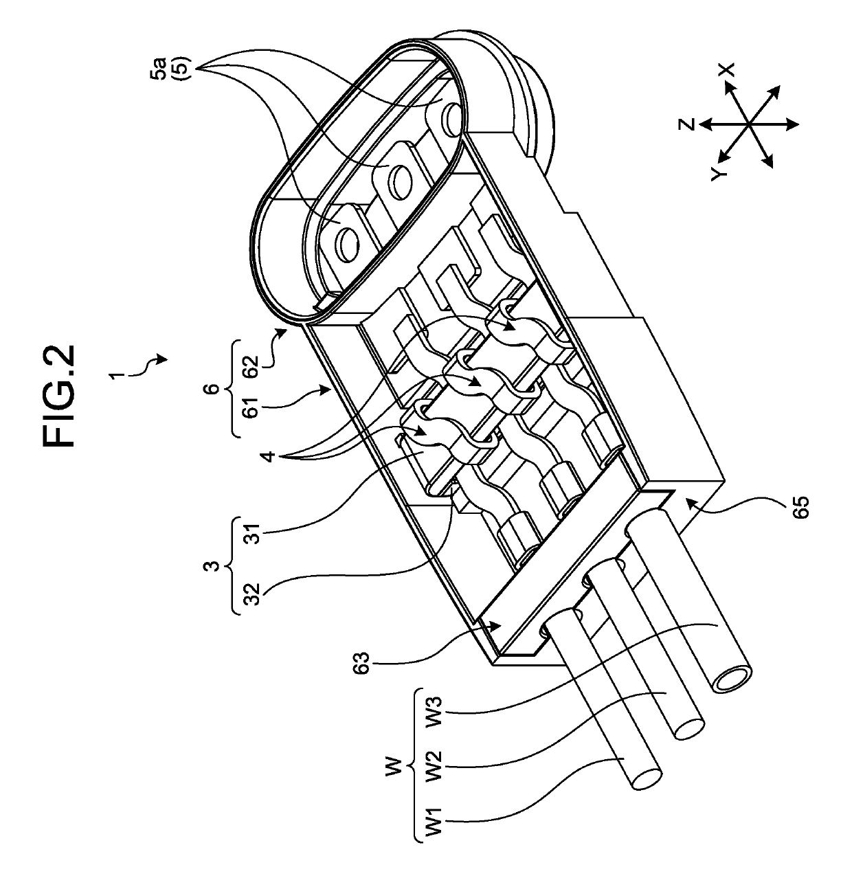
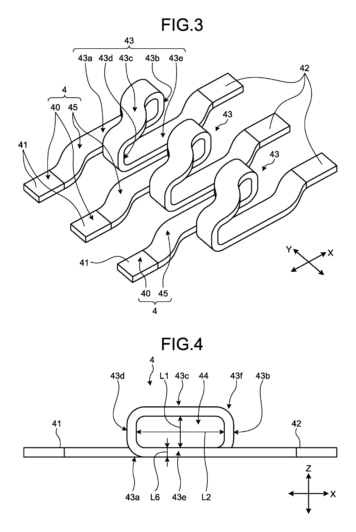
[0029]A first embodiment of the present invention will be described with reference to FIGS. 1 to 14. The present embodiment relates to the conductor unit. FIG. 1 is a plan view illustrating a wire harness according to the first embodiment. FIG. 2 is a perspective view illustrating a conductor unit according to the first embodiment. FIG. 3 is a perspective view illustrating busbars according to the first embodiment. FIG. 4 is a side view illustrating the busbars according to the first embodiment. FIG. 5 is a perspective view illustrating a core according to the first embodiment. FIG. 6 is a side view illustrating the core according to the first embodiment. FIG. 7 is a perspective view illustrating a state of insertion of a first core constituent portion according to the first embodiment. FIG. 8 is a perspective view illustrating a state of bonding of the core according to the first embodiment. FIG. 9 is a perspective view illustrating a cored electric cable according to the first emb...

second embodiment

[0058]A second embodiment of the present invention will be described with reference to FIG. 15. In the second embodiment, components having the same functions as those described above in the first embodiment will be assigned with identical reference numerals thereto, and the description thereof will not be repeated. The conductor unit 1 of the second embodiment differs from the conductor unit 1 of the first embodiment described above in that the busbars 4 and the core 3 are disposed at intermediate portions of the electric wires W. FIG. 15 is a perspective view illustrating the conductor unit according to the second embodiment.

[0059]As illustrated in FIG. 15, in the conductor unit 1 according to the second embodiment, the electric wires W are connected not only to the first end portions 41 of the busbars 4, but also to the second end portions 42 thereof. That is, the busbars 4 are interposed at the intermediate portions of the electric wires W. The conductor unit 1 of the present em...


PUM

PropertyMeasurementUnit
conductoraaaaaaaaaa
magneticaaaaaaaaaa
shapeaaaaaaaaaa

Abstract

A conductor unit includes: a plurality of conductors each including a conducting portion covered with an insulating coating; an annular core that includes a first core constituent portion and a second core constituent portion combined with the first core constituent portion, and that interposes the conductors between the first core constituent portion and the second core constituent portion; and a holding member that makes the first core constituent portion and the second core constituent portion press and hold the conductors therebetween.

Description

CROSS-REFERENCE TO RELATED APPLICATION(S)[0001]The present application claims priority to and incorporates by reference the entire contents of Japanese Patent Application No. 2017-042785 filed in Japan on Mar. 7, 2017.BACKGROUND OF THE INVENTION1. Field of the Invention[0002]The present invention relates to a conductor unit.2. Description of the Related Art[0003]Techniques have conventionally been developed to provide a core in a circuit. Japanese Patent Application Laid-open No. 2009-158534 discloses a technique of a reactor including a hollow tubular core having a hollow portion through which a busbar forming a circuit for performing power conversion is inserted and the busbar around which the core is disposed. The core of Japanese Patent Application Laid-open No. 2009-158534 is fixed to a circuit device body using a fixing device.[0004]If a conductor is movable relative to the core, a friction between the conductor and the core may damage a coating of the conductor during conveya...

Claims


Application Information

Patent Timeline
Patent Type & Authority Patents(United States)
IPC IPC(8): H01R4/04H01R13/405H01B1/22H05K3/32H01R11/09H01R13/03
CPCH01R4/04H01B1/22H01R13/405H05K3/321H05K2201/10272H01R11/09H01R13/03H05K2201/0224H01F3/00
Inventor IIZUKA, HAYATONAKAI, SATOSHIKAYO, KAZUMAAIHARA, HIROSHI
Owner YAZAKI CORP
Why Eureka
Try Eureka