

Flyback power converter circuit and secondary side controller circuit thereof
a power converter and circuit technology, applied in the direction of power conversion systems, dc-dc conversion, climate sustainability, etc., can solve the problems of reducing the coupling effect, extra power consumption, slow transient,
- Summary
- Abstract
- Description
- Claims
- Application Information
AI Technical Summary
Benefits of technology
Problems solved by technology
Method used
Image


Examples
Embodiment Construction
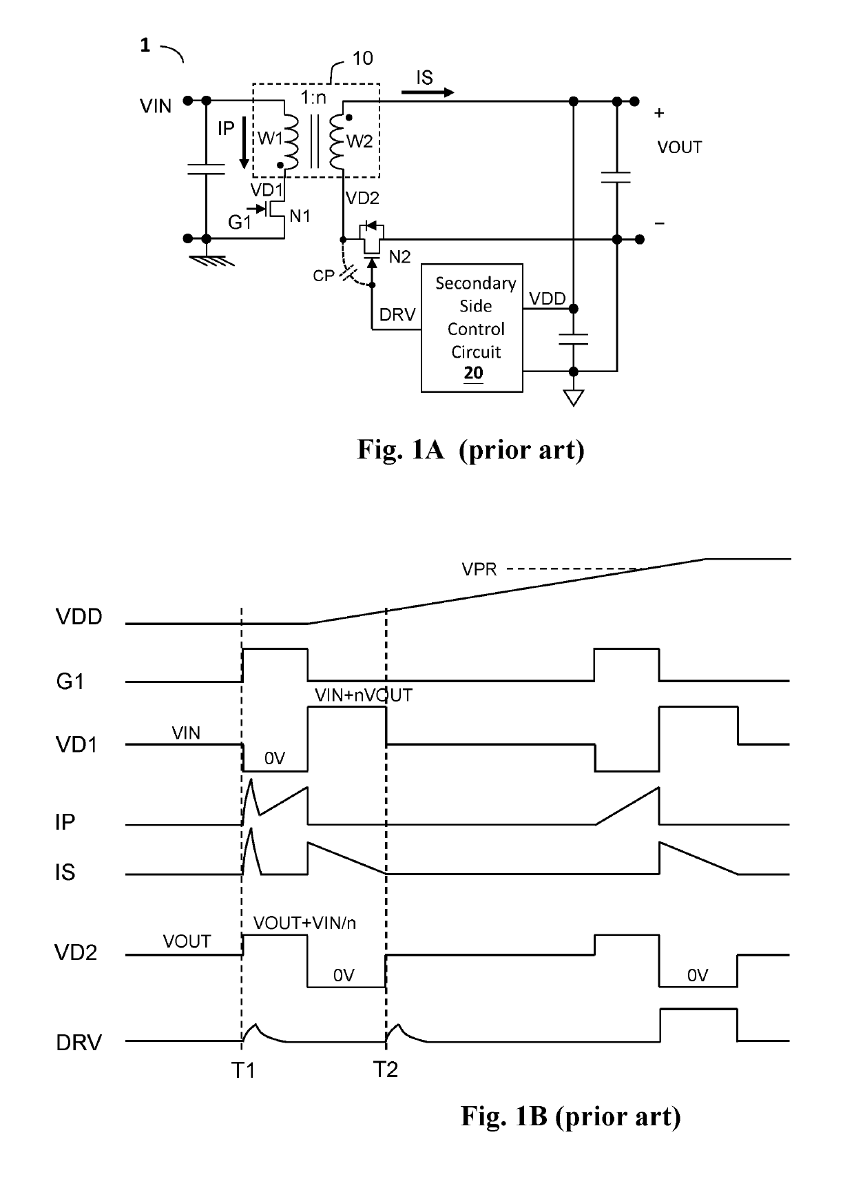
[0033]The drawings as referred to throughout the description of the present invention are for illustration only, to show the interrelations between the circuits and the signal waveforms, but not drawn according to actual scale.
[0034]FIG. 3 shows one embodiment of the flyback power converter circuit according to the present invention (flyback power converter circuit 3). The flyback power converter circuit 3 comprises a transformer 10, a power switch N1, a synchronous rectifier (SR) switch N2, and a secondary side control circuit 20. The transformer 10 includes a primary side winding W1 for receiving an input voltage VIN and a secondary side winding W2 for generating an output voltage VOUT. The power switch N1, which is coupled to the primary side winding W1 and controlled by a primary side control circuit, controls a conduction time of the primary side winding W1 by for example but not limited to PWM control scheme. The synchronous rectifier (SR) switch N2, which is coupled to the se...
PUM
 Abstract
Description
Claims
Application Information