System and method for protecting a liquid crystal display by controlling ion migration

a technology of liquid crystal display and control system, which is applied in the field of liquid crystal display control, can solve the problems of reducing optical performance, affecting the performance of lcd devices, and deteriorating the liquid crystal layer of such lcos displays (and also those of other lcd devices) over time, and achieves the effect of facilitating driving

Active Publication Date: 2019-10-01
OMNIVISION TECH INC
View PDF9 Cites 0 Cited by
  • Summary
  • Abstract
  • Description
  • Claims
  • Application Information

AI Technical Summary

Benefits of technology

[0007]The present invention overcomes the problems associated with the prior art by providing a display device and method that facilitates driving a border area surrounding a display area of a pixel array with display-protection images. The display-protection images impose barriers to ion migration and allow ion migration to be controlled in the liquid crystal layer, which prevent ions from accumulating in corners of the liquid crystal display and causing permanent defects. The present invention also overcomes the problems associated with the prior art by providing a display device that includes a border area with liquid crystal alignment direction(s) that promote ion migration away from the display area.
[0012]A method for driving a liquid crystal display having a pixel array and a liquid crystal layer disposed over the pixel array is also disclosed. The method includes the steps of defining a display area of the pixel array, where the display area is associated with a first set of pixels of the pixel array, and defining a border area of the pixel array, where the border area is associated with a second set of pixels of the pixel array. The method further includes receiving image data and display-protection data, driving the first set of pixels based on the image data to display images intended to be viewed by an audience on the display area, and driving the second set of pixels based on the display-protection data to display display-protection images on the border area. The display-protection images inhibit ion migration in the liquid crystal layer.
[0015]A method for manufacturing a liquid crystal display is also disclosed. Such a method includes the steps of providing a substrate, forming a first set of pixels on the substrate, where the first set of pixels correspond to a display area of a pixel array, and forming a second set of pixels on the substrate, where the second set of pixels corresponds to a border area of the pixel array. The method also includes the steps of forming circuitry facilitating the assertion of image data on the first set of pixels to display images intended to be viewed by an audience, forming circuitry facilitating the assertion of display protection images on the second set of pixels, and forming at least one ion-migration control feature on the substrate and at least partially surrounding the first set of pixels. In a particular method, the step of forming the at least one ion-migration control feature includes forming at least one ion reservoir at least partially surrounding the border area. In another particular method, the border area at least partially surrounds the display area and the step of forming the at least one ion-migration control feature comprises forming at least some of the pixels of the second set to be smaller than adjacent pixels of the first set.

Problems solved by technology

The liquid crystal layer of such LCOS displays (and also those of other LCD devices) degrades over time.
Indeed, even after several hundred hours of operation, LCD devices often display such non-uniformity problems as image retention or sticking, flares (unwanted lighter areas), edge bleeding, permanent black (PB) areas, etc.
These defects result in diminished optical performance, costly warranty repairs / recalls, and / or lost customers.

Method used


Image

  • System and method for protecting a liquid crystal display by controlling ion migration
  • System and method for protecting a liquid crystal display by controlling ion migration
  • System and method for protecting a liquid crystal display by controlling ion migration

Examples


Embodiment Construction

[0053]The present invention overcomes the problems associated with the prior art, by providing a display driver and display that facilitates controlling ion migration in the liquid crystal layer and promotes ion migration away from the display area of a pixel array. In the following description, numerous specific details are set forth (e.g., specific driving patterns, pixel layouts, shapes, etc.) in order to provide a thorough understanding of the invention. Those skilled in the art will recognize, however, that the invention may be practiced apart from these specific details. In other instances, details of well-known liquid crystal displays and display driving practices and components (e.g., pixel circuitry layouts, wafer processing techniques, data processing, routine optimization, etc.) have been omitted, so as not to unnecessarily obscure the present invention.

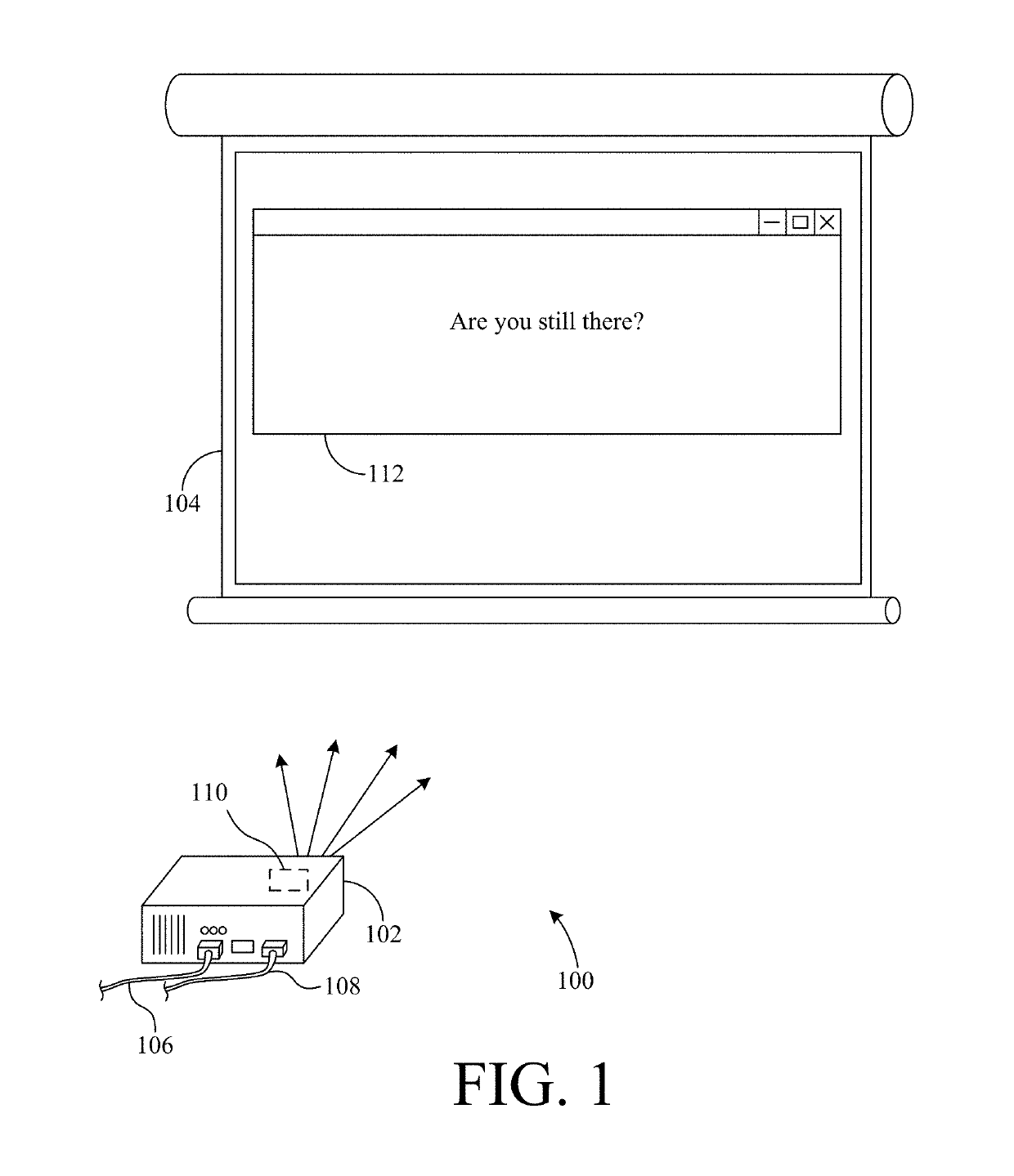
[0054]FIG. 1 shows a projector system 100, including a projector 102 and a screen 104. Projector 102 is connected to a p...


PUM

PropertyMeasurementUnit
voltageaaaaaaaaaa
areaaaaaaaaaaa
voltageaaaaaaaaaa

Abstract

A liquid crystal display includes a display area and a border area at least partially surrounding the display area, where the display area displays images for viewing and the border area displays display-protection images, which are used to control ion migration in the liquid crystal layer. In a more particular embodiment, the border area displays a series of checkerboard pattern(s), where the checkerboard patterns can alternate between initial and inverted values. The display-protection images protect the liquid crystal display from migrating ions accumulating in particular regions of the pixel array and causing permanent defects in the display area. A liquid crystal display that includes a liquid crystal alignment layer having a plurality of liquid crystal alignment directions is also disclosed. The customized liquid crystal alignment director(s) over the border area promote ion migration away from the display area.

Description

CROSS REFERENCE TO RELATED APPLICATIONS[0001]This application is a divisional of co-pending U.S. patent application Ser. No. 15 / 357,920, filed Nov. 21, 2016 and having at least one common inventor, which is incorporated by reference herein in its entirety.BACKGROUND OF THE INVENTIONField of the Invention[0002]This invention relates generally to liquid crystal displays, and more particularly to controlling ion migration in the liquid crystal layer of a liquid crystal display.Description of the Background Art[0003]Reflective and transmissive liquid crystal displays (LCDs) are used in video projectors, rear projection televisions, computer displays, and other devices as a means for producing high-quality imagery. One type of LCD is a liquid crystal on silicon (LCOS) display. Such LCOS displays typically include a silicon substrate, integrated circuitry, a plurality of pixel mirrors, and a liquid crystal layer disposed between the pixel mirrors and an opposite transparent electrode form...

Claims


Application Information

Patent Timeline
Patent Type & Authority Patents(United States)
IPC IPC(8): G02F1/1337G02F1/1333G09G3/36G02F1/1362
CPCG02F1/133734G02F1/133753G02F1/133723G02F1/1337G02F1/133719G02F1/133711G02F1/133788G02F2001/133757G02F2202/36G09G2310/0232G02F2201/501G02F2001/133388G02F2203/01G02F1/136213G02F2001/133776G02F2201/50G09G3/3655G02F2001/133769G09G2300/0426G02F1/133388G02F1/133757G02F1/133769G02F1/133776
Inventor WALKER, CHRISTOPHER MORGANWENG, LIBOCELLEK, ORAY ORKUNZHANG, MINGQIAN, YINTAI, DYSON HSIN-CHIHFAN, REGIS
Owner OMNIVISION TECH INC
Why Eureka
Try Eureka