Fuel supply system for a gas burner assembly

a technology of gas burner and fuel supply system, which is applied in the direction of burner control devices, gaseous heating fuel, domestic stoves or ranges, etc., can solve the problem of increasing the risk of carbon monoxide exposure, the practicability limit of primary air of a normally aspirated gas burner, and the cost or complexity of conventional fuel supply systems including such forced air supply systems

Active Publication Date: 2020-06-09
HAIER US APPLIANCE SOLUTIONS INC
View PDF57 Cites 5 Cited by
  • Summary
  • Abstract
  • Description
  • Claims
  • Application Information

AI Technical Summary

Problems solved by technology

Because the nominal fuel pressure in households is relatively low, there is a practical limit to the amount of primary air a normally aspirated gas burner can entrain.
However, in the event that the forced air supply fails to provide sufficient primary air for any reason, a fuel-rich mixture may be combusted in the fuel chamber, thereby increasing the risk of carbon monoxide exposure.
Thus, conventional fuel supply systems including such forced air supply systems often require costly or complicated flow sensors or flow sensing schemes for regulating operation in the event of component failures.

Method used


Image

  • Fuel supply system for a gas burner assembly
  • Fuel supply system for a gas burner assembly
  • Fuel supply system for a gas burner assembly

Examples


Embodiment Construction

[0018]Reference now will be made in detail to embodiments of the invention, one or more examples of which are illustrated in the drawings. Each example is provided by way of explanation of the invention, not limitation of the invention. In fact, it will be apparent to those skilled in the art that various modifications and variations can be made in the present invention without departing from the scope or spirit of the invention. For instance, features illustrated or described as part of one embodiment can be used with another embodiment to yield a still further embodiment. Thus, it is intended that the present invention covers such modifications and variations as come within the scope of the appended claims and their equivalents.

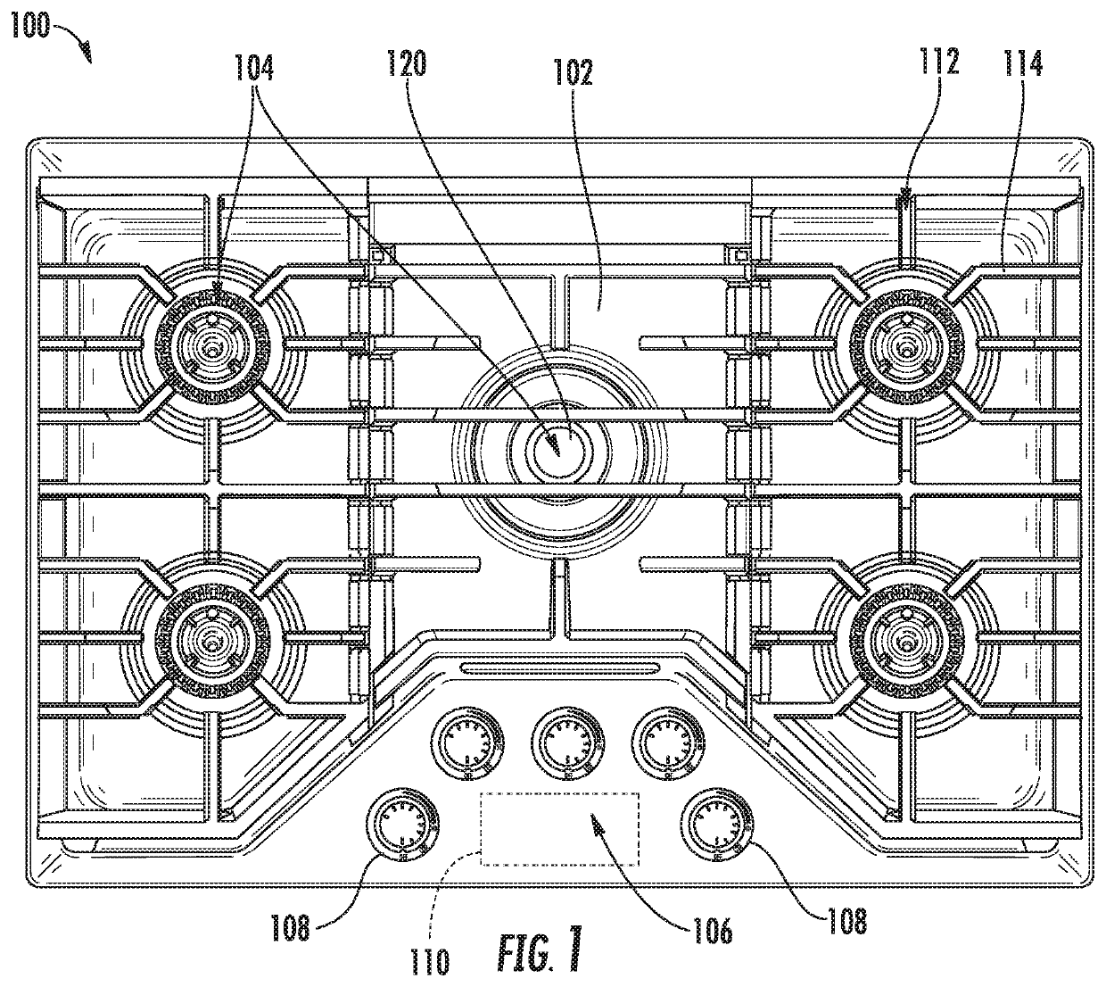
[0019]The present disclosure relates generally to a gas burner assembly for a cooktop appliance 100. Although cooktop appliance 100 is used below for the purpose of explaining the details of the present subject matter, one skilled in the art will appreciate...


PUM


Abstract

A fuel supply system for a gas burner assembly includes a fuel supply, a forced air supply, and an injection assembly positioned proximate the gas burner assembly for providing a flow of combustion air and fuel through an inlet into a fuel chamber. A pressure controlled valve is operably coupled with the fuel supply and the forced air supply, the pressure controlled valve being configured for stopping the flow of fuel when a pressure of the flow of combustion air drops below a predetermined pressure, potentially indicating a malfunction or failure of the forced air supply.

Description

FIELD OF THE INVENTION[0001]The present subject matter relates generally to gas burner assemblies, and more particularly, to fuel supply systems for supplying a mixture of fuel and air into gas burner assemblies.BACKGROUND OF THE INVENTION[0002]Gas burners are commonly used on the cooktops of household gas cooking appliances including e.g., range ovens and cooktop appliances built into cabinetry. For example, gas cooktops traditionally have at least one gas burner positioned at a cooktop surface for use in heating or cooking an object, such as a cooking utensil and its contents. Gas burners generally include an orifice that directs a flow of gaseous fuel into a fuel chamber. Between the orifice and the fuel chamber, the gaseous fuel entrains air, and the gaseous fuel and air mix within the fuel chamber before being ignited and discharged out of the fuel chamber through a plurality of flame ports.[0003]Normally aspirated gas burners rely on the energy available in the form of pressur...

Claims


Application Information

Patent Timeline
Patent Type & AuthorityPatents(United States)
IPC IPC(8): F24C3/08F24C3/12F23N5/18
CPCF24C3/122F24C3/082F24C3/085F24C3/126F23D2208/00F23N2005/182F23N2005/181
InventorPALLER, HANS JUERGEN
OwnerHAIER US APPLIANCE SOLUTIONS INC