
Downhole cutting tool and method of use
a cutting tool and drilling tool technology, applied in the direction of drilling accessories, borehole/well accessories, earthwork drilling and mining, etc., can solve the problems of reducing the production of hydrocarbons, reducing the productive life of wells, and time-consuming and expensive processes
- Summary
- Abstract
- Description
- Claims
- Application Information
AI Technical Summary
Benefits of technology
Problems solved by technology
Method used
Image

Examples
Embodiment Construction
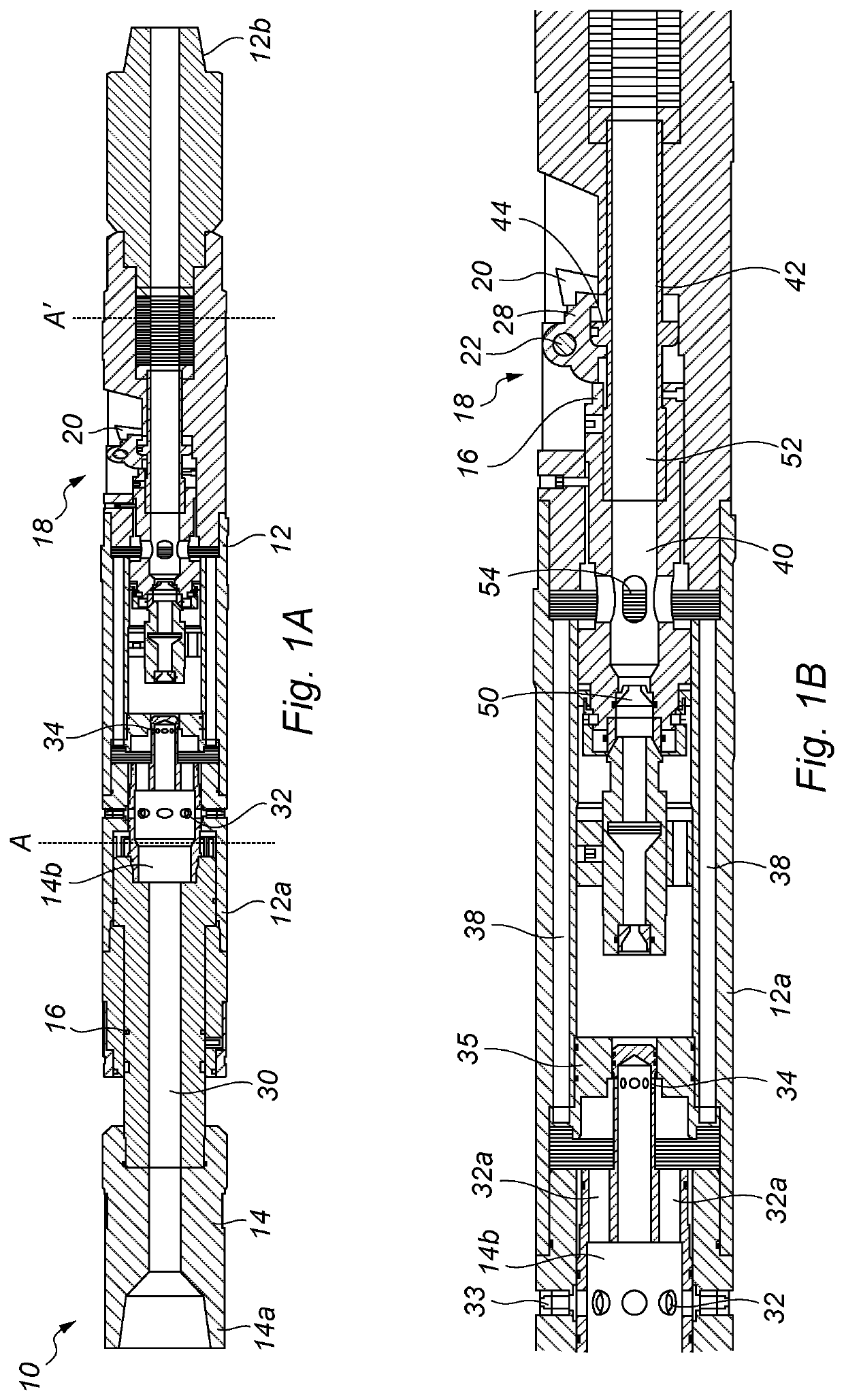
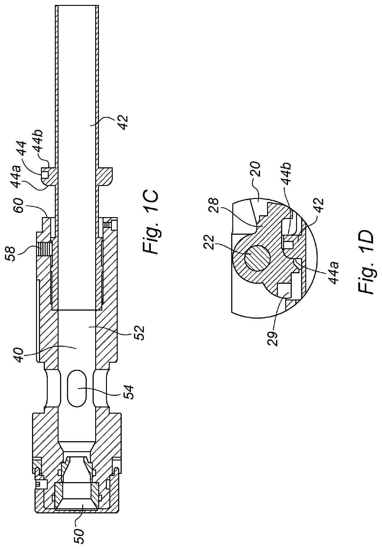
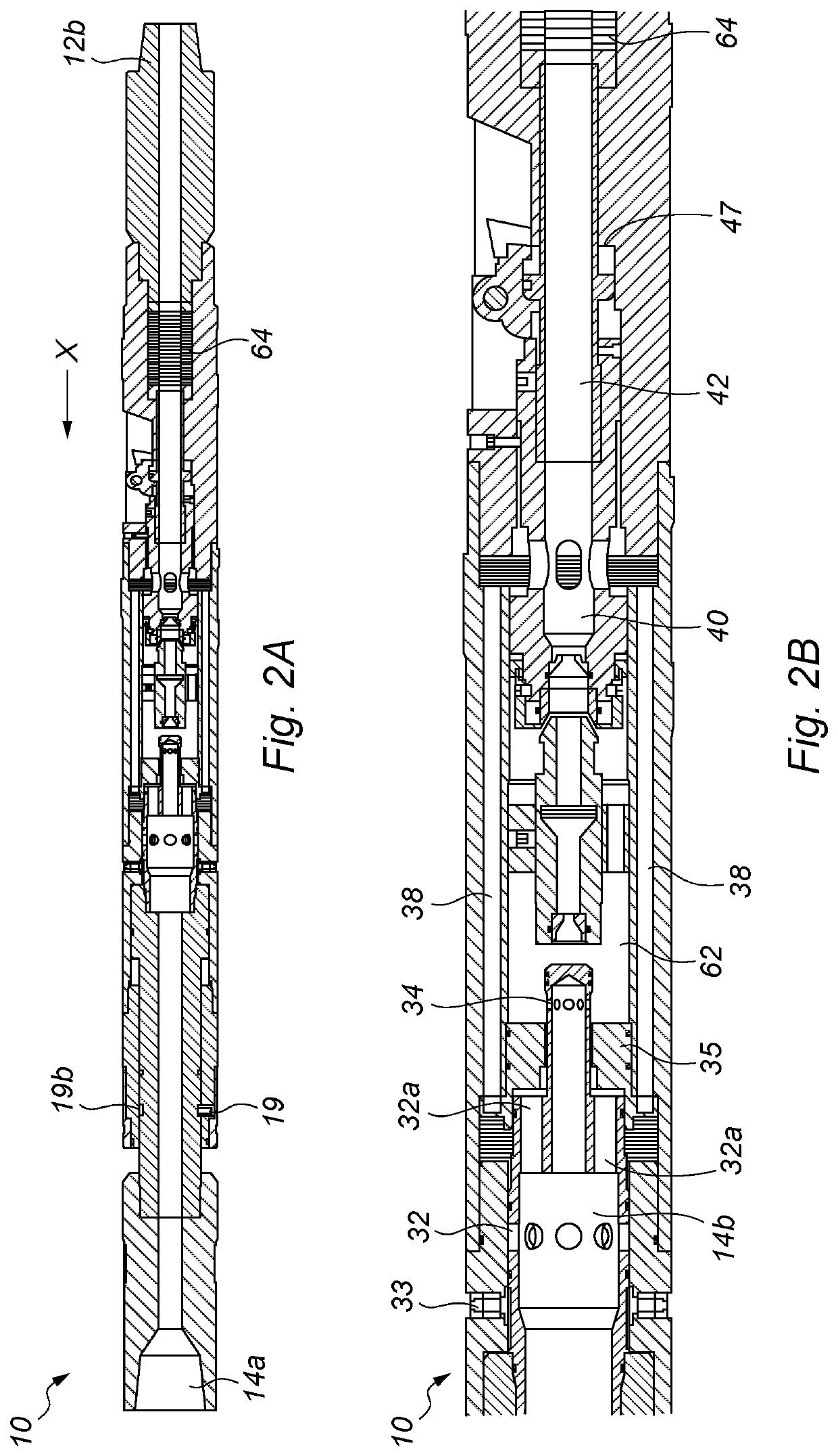
[0195]FIGS. 1A, 2A and 3A are longitudinal sectional views of a downhole tool in accordance with a first embodiment of the invention in different phases of operation.
[0196]FIG. 1A is a longitudinal section through the downhole tool 10. The downhole tool 10 has an elongate body 12 and a mandrel 14.
[0197]A first end 14a of the mandrel 14 is configured to be coupled to an upper tool string such as a drill string (not shown). The second end 14b of the mandrel is axially movably mounted in the body 12.
[0198]A first end 12a of the body 12 surrounds a portion of mandrel 14. The second end 12b of the body is configured to be coupled to a lower tool string such as a drill string (not shown). The lower tool string may be connected to downhole tool located further downhole. The second end 12b of the body is designed for insertion into a downhole tubular first.
[0199]The mandrel 14 is configured to be axially moveable in the body and is held in a first position by sheer screws 16. The tool body ...
PUM
 Abstract
Description
Claims
Application Information