
Downhole Cut and Pull Tool and Method of Use

Active Publication Date: 2020-07-16
ARDYNE HLDG LTD
View PDF0 Cites 7 Cited by
  • Summary
  • Abstract
  • Description
  • Claims
  • Application Information

AI Technical Summary

Benefits of technology

The present invention provides a downhole tool that can be easily deployed downhole and adapt to different casing diameters for quick removal. The tool has improved productivity or efficiency by being capable of reliably performing multiple casing gripping and cutting actions once deployed. It includes a gripping mechanism and cutting mechanism that are axially spaced apart to mitigate vibration effects or chattering on the tool. The close proximity of the gripping mechanism to the cutting mechanism preserves the structural integrity of the knives and extends their life span by avoiding damage due to vibration. The tool may comprise a receptacle connected to it for easy transportation of casing cuttings back to surface.

Problems solved by technology

Over time, which may be several decades, the production of hydrocarbons reduces until the production rate is no longer economically viable, at which point the well has reached the end of its productive life.
This can be a time consuming and expensive process.
This can be cumbersome and time-consuming.

Method used


Image

  • Downhole Cut and Pull Tool and Method of Use
  • Downhole Cut and Pull Tool and Method of Use
  • Downhole Cut and Pull Tool and Method of Use

Examples


Embodiment Construction

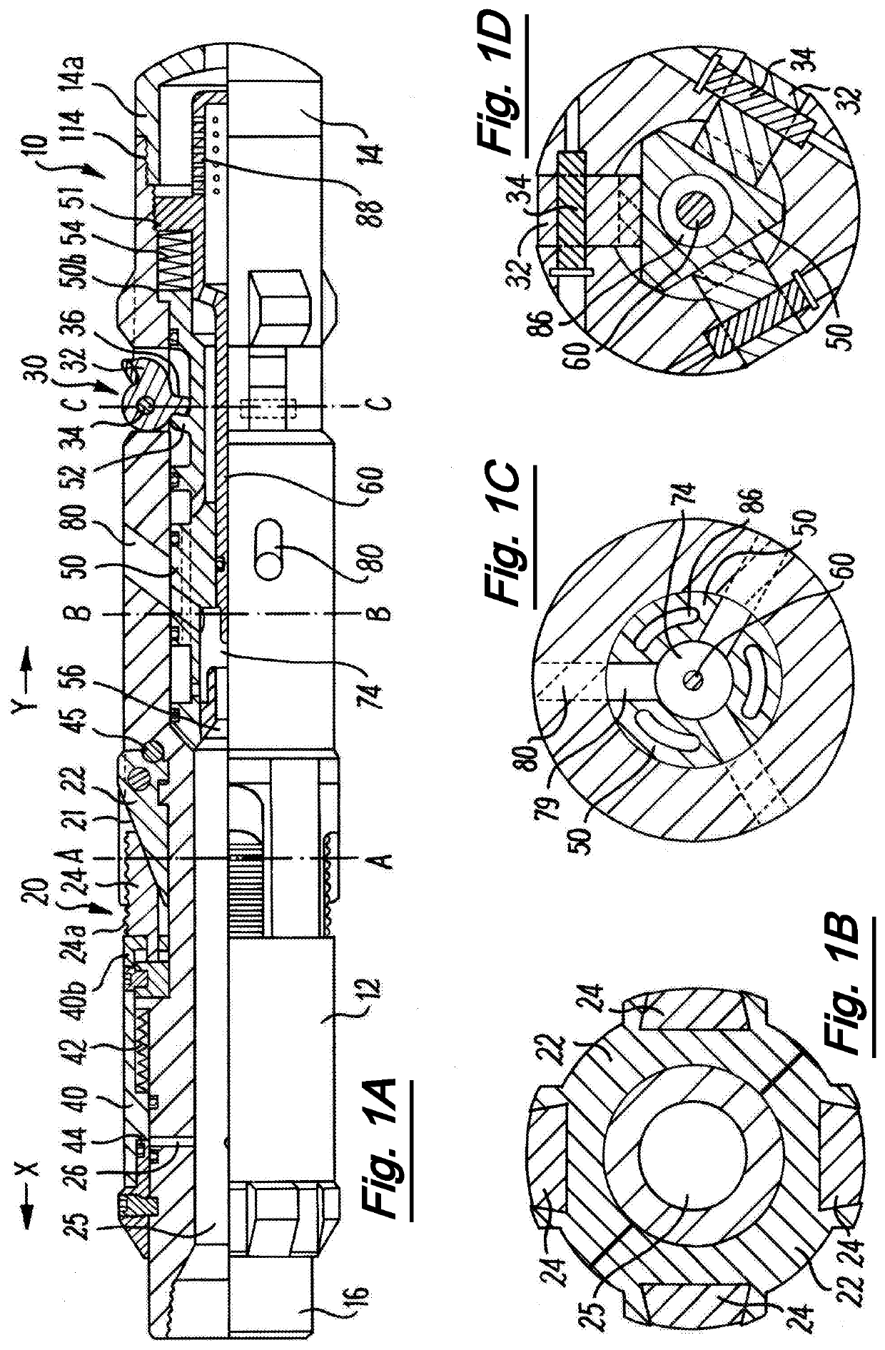
[0194]The tool is used in a well borehole lined with a well casing. It will be appreciated that this is only an example use and the tool may be used in other applications in gripping and cutting tubular structures.

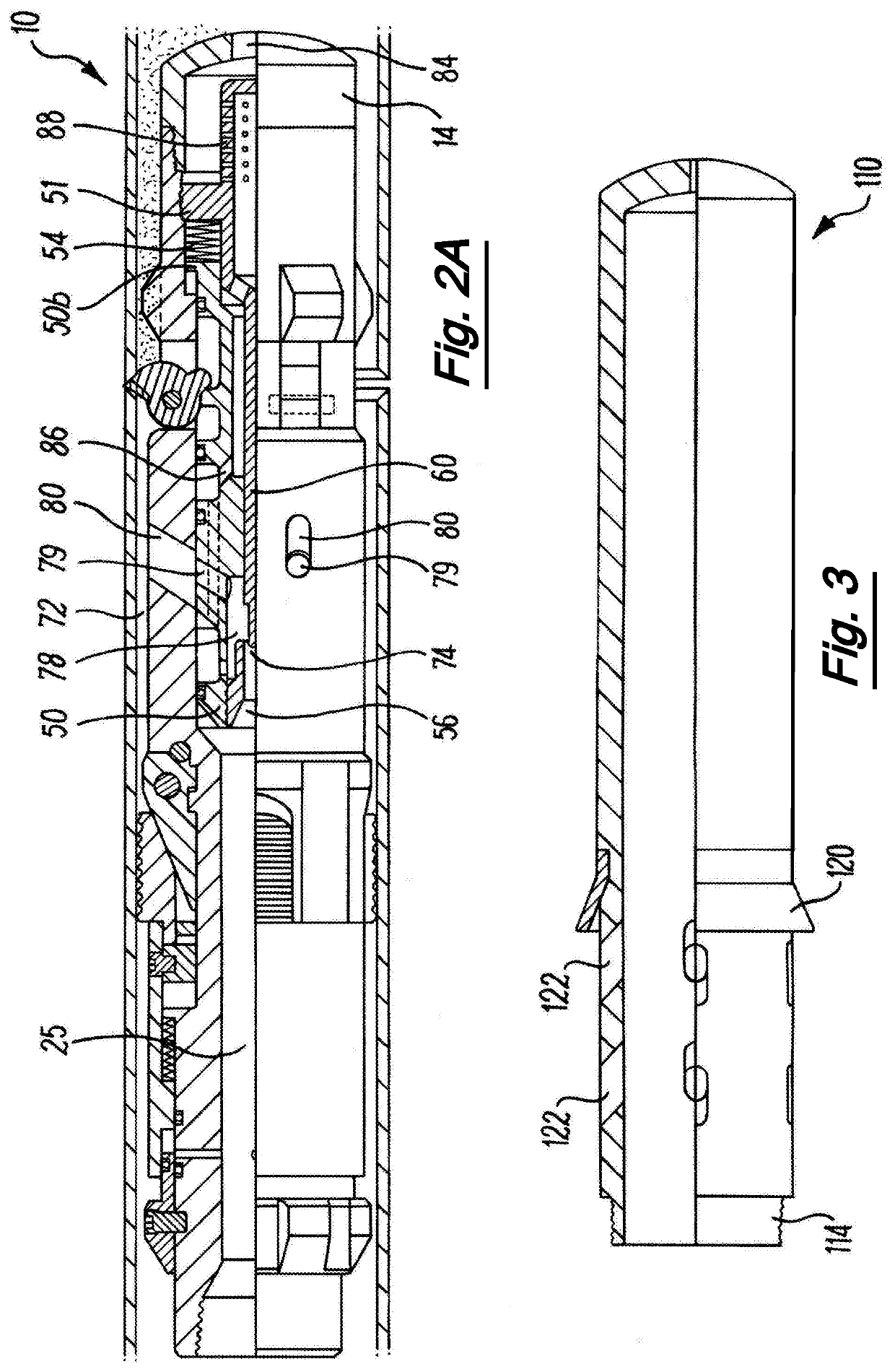
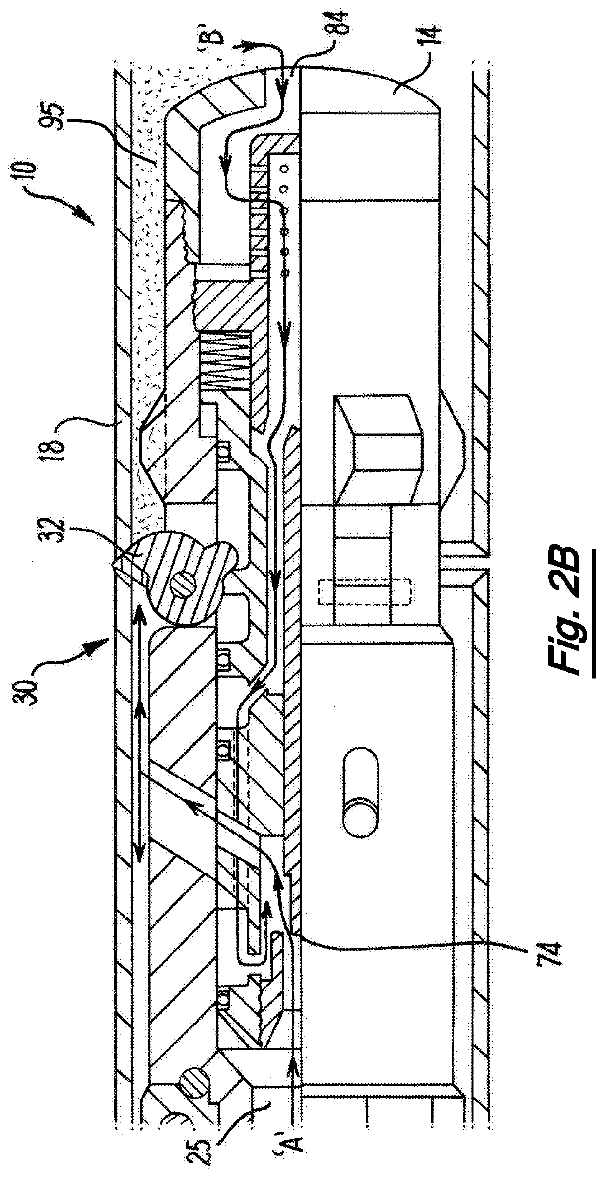
[0195]FIGS. 1A and 2A are sectional views of a downhole tool in accordance with a first embodiment of the invention in different phases of operation.

[0196]FIG. 1A is a longitudinal section through the downhole tool 10. The downhole tool 10 has an elongate body 12 with a first end 14 and a second end 16. The first end 14 is designed for insertion into the wellbore first. The second end 16 is configured to be coupled to a tool string. The tool body 12 comprises a gripping mechanism 20 to secure the tool within the wellbore casing and a cutting mechanism 30 configured to cut the casing.

[0197]The gripping mechanism 20 comprises a cone 22 circumferentially disposed about a section of the downhole tool 10. FIG. 1B shows a cross-section of line A-A′ of FIG. 1A. A plurality of sli...


PUM


Abstract

The invention provides a downhole tool for cutting a wellbore casing. The downhole tool comprises a gripping mechanism for gripping a section of wellbore casing and a cutting mechanism configured to cut the casing. The grip mechanism is configured to grip a range of casing diameters.

Description

[0001]The present invention relates to a downhole tool and method of use, and in particular to downhole tubular cutting and pulling tools. A particular aspect of the invention relates to mechanisms to grip and cut a wellbore casing.BACKGROUND TO THE INVENTION[0002]In the course of constructing an oil or gas well, a hole is drilled to a pre-determined depth. The drilling string is then removed and a metal tubular or casing is run into the well and is secured in position using cement.[0003]This process of drilling, running casing and cementing is repeated with successively smaller drilled holes and casing sizes until the well reaches its target depth. At this point, a final tubular or tubing is run into the well.[0004]During production hydrocarbon flow through the tubing and are collected at surface. Over time, which may be several decades, the production of hydrocarbons reduces until the production rate is no longer economically viable, at which point the well has reached the end of ...

Claims


Application Information

Patent Timeline
IPC IPC(8): E21B29/00E21B31/16E21B31/20E21B23/01
CPCE21B29/005E21B31/16E21B31/20E21B23/01
Inventor TELFER, GEORGEWARDLEY, MICHAELFAIR-WEATHER, ALAN
Owner ARDYNE HLDG LTD
Learn More