Cylinder block cooling arrangement for multi-cylinder internal combustion engine

a multi-cylinder, internal combustion engine technology, applied in the direction of cylinders, machines/engines, mechanical equipment, etc., can solve the problems of thermal expansion differences, non-uniform temperature distribution on the combustion chamber surface, and maintenance of generally consistent cylinder temperatures, so as to facilitate filling and draining of water jackets and reduce air entrapment

Inactive Publication Date: 2005-10-27
HONDA MOTOR CO LTD
View PDF9 Cites 75 Cited by
  • Summary
  • Abstract
  • Description
  • Claims
  • Application Information

AI Technical Summary

Benefits of technology

[0028] In accordance with the present invention, an insert is separately manufactured and disposed in the engine block water jacket. The insert includes a plurality of arcuate members and a plurality of support members, which are preferably integrally formed as a single part. The insert is disposed in the water jacket so as to separate the water jacket into two or more vertically or axially offset sub-jackets or portions. The insert separates the water jacket into a plurality of cooling layers in the direction of the cylinder axis, and thereby provides a desired coolant flow pattern. At least some of the support members are disposed adjacent inter-bore or conjoined portions that require additional cooling, and serve to guide coolant flow toward these siamesed or conjoined wall portions.
[0029] In further accordance with the present invention, the arcuate members have holes or notches formed therein to permit fluid in vertically adjacent, but otherwise separate, portions of the water jacket to flow therethrough. The holes facilitate filling and draining of the water jacket with reduced entrapment of air or fluid, and permit engine speed-dependent coolant flow distribution among layers of the water jacket volume. More particularly, the holes are arranged so that coolant flows in an upper portion of the water jacket when engine speed is below a pre-defined engine speed and, as engine speed increases, an increasing amount of coolant flows into the water jacket lower portion through the holes, and re-emerges to the water jacket upper portion via further holes at desired downstream locations. Accordingly, the insert of the present invention allows the cooling characteristics to respond to operational requirements of the engine.

Problems solved by technology

Unfortunately, due to the structure of such cylinder blocks and the flow of combustion gases, temperature differences exist between different sides of the cylinders (i.e., intake v. exhaust), different ends of the cylinders (top v. bottom) and between different cylinders (i.e., end cylinders v. internal cylinders).
These temperature differences are not addressed in the aforementioned conventional cooling arrangement, and create problems in maintaining generally consistent cylinder temperatures.
For example, the heat path to coolant flow from the siamese regions (i.e., conjoined regions of adjacent cylinders) is longer than the heat path to coolant flow from other areas, and inevitably results in non-uniform temperature distribution on the combustion chamber surface.
This, in turn, causes thermal expansion differences between inner, conjoined portions of the cylinder walls, which lack direct contact with a cooling water passage, and external portions of the cylinder walls, which are in direct contact with a cooling water passage.
Temperature differences in the cylinder wall may result in engine operational problems.
For example, if the cylinder wall is distorted due to differing amounts of thermal expansion, the piston ring at the upper side of the piston, which reciprocates vertically within the cylinder, does not uniformly seal to the cylinder wall but rather will partially stick to the cylinder wall at some locations and loosely slide over the cylinder wall at other locations.
In addition to the problems associated with thermal deformation, an auto-ignition tendency in spark ignition engines is related to combustion chamber surface temperature.
Furthermore, efficient installation of such guide ribs during mass production presents a major obstacle.
However, this design significantly complicates high-pressure aluminum die casting, which is widely used to manufacture cylinder blocks.
Unfortunately, the passage thickness at the bottom is limited by the manufacturability, or imposes significant cost increases, and therefore the Boggs structure has proven to be commercially or functionally impractical.
However, the proposed method is expensive and has a negative impact on combustion gas sealing.
Furthermore, it does not affect temperature uniformity and shortening of engine warm-up.
The ideas as described in embodiments 1 to 10 will increase cylinder wall temperature of lower portion, which will adversely affect piston heat dissipation capability and engine performance due to charge heating.
Embodiments 45 to 48 address high cylinder wall temperature problems at high engine speed, but require devices to adjust flow rate, which increases the cost and requires a new engine block design and a new coolant flow layout.

Method used


Image

  • Cylinder block cooling arrangement for multi-cylinder internal combustion engine
  • Cylinder block cooling arrangement for multi-cylinder internal combustion engine
  • Cylinder block cooling arrangement for multi-cylinder internal combustion engine

Examples


second embodiment

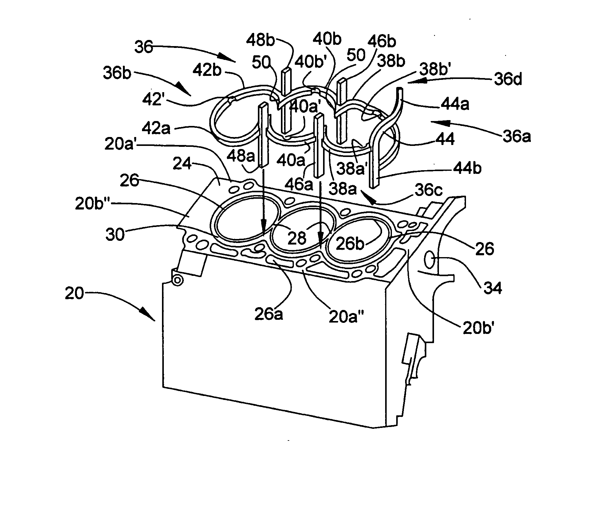
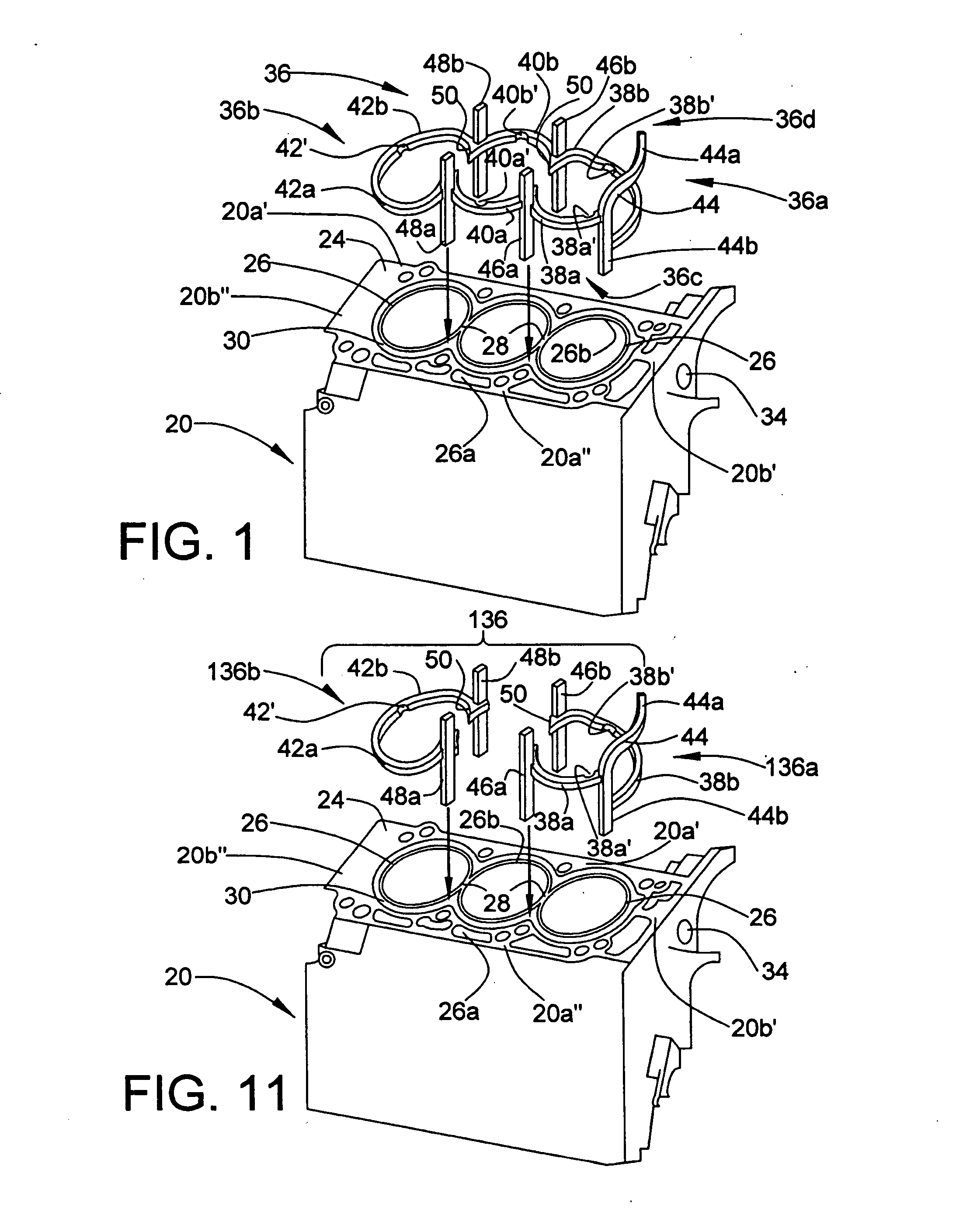
[0076] The insert 136 includes a first insert member 136a and a second insert member 136b. The first insert member 136a includes the first support member 44, the first arcuate members 38a, 38b, and the second and fourth support members 46b, 46a. Similarly, the second insert member 136b includes the third arcuate members 42a, 42b and the third and fifth support members 48b, 48a. The second arcuate members 40a, 40b are not provided by the insert 136. Accordingly, the insert 136 is installed in the water jacket 30 by inserting the first insert member 136a into the first end of the water jacket, and by inserting the second insert member 136b into the opposite or second end of the water jacket.

first embodiment

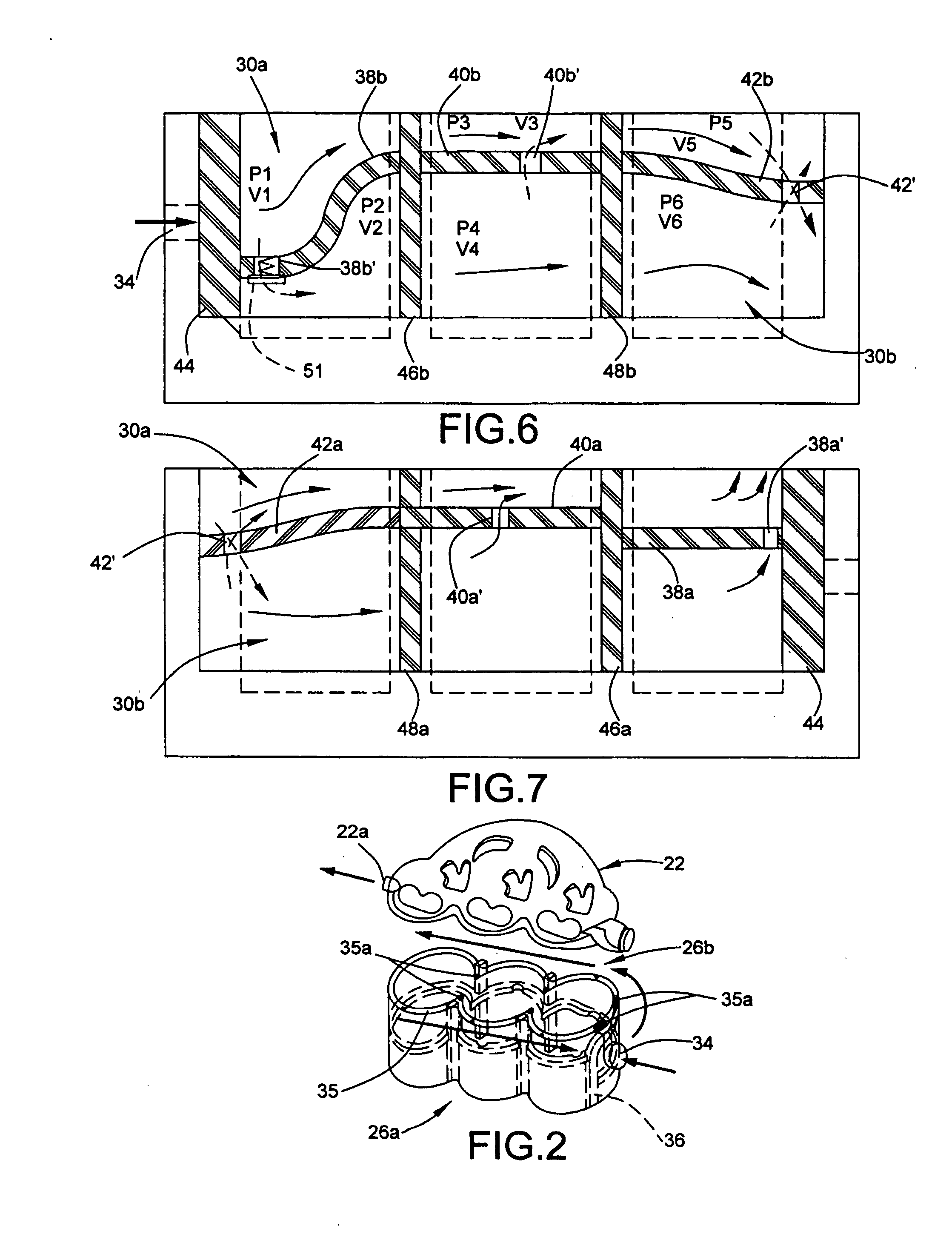
[0077] With reference to FIGS. 12-13, wherein flow through the water jacket 30 with the insert 136 is illustrated, it has been found that the insert 136 provides many of the same advantages as the present invention. For example, when engine speed is low, the coolant flows primarily in the upper portion 30a of the water jacket. Although there tends to be some mixing of coolant due to the lack of isolation between the upper and lower portions 30a, 30b of the water jacket at the middle portion of the engine block, the fluid tends to continue moving in the same direction as it flows across the second support member 46b toward the fourth support member 48b, so this mixing is somewhat minimized at low speeds. At higher engine speeds, in which the coolant is moving faster in the upper portion 30a of the water jacket, this mixing is more pronounced, but even in this case the coolant flow remains stratified to a certain extent, and mixing tends to be primarily due to the previously mentioned...


PUM


Abstract

An insert for a siamese-type internal combustion engine that separates a water jacket surrounding the cylinders into an upper portion and a lower portion. Below a predetermined engine speed coolant flows primarily in the upper water jacket portion so as to provide enhanced cooling at the upper portions of the cylinders. Above a predetermined engine speed coolant is introduced into the lower water jacket portion from the upper water jacket portion so as to provide improved cooling of the lower cylinder portions, without compromising cooling of the upper cylinder portions or the conjoined cylinder wall portions. The water jacket insert enhances coolant flow velocity at the siamesed or conjoined portions of the cylinder walls, and directs incoming initially coolant over the exhaust-side of the cylinders. Use of the insert reduces circumferential and axial intra-cylinder temperature deviations as well as inter-cylinder temperature deviations.

Description

BACKGROUND OF THE INVENTION [0001] 1. Field of the Invention [0002] The present invention generally relates to internal combustion engines and, more particularly, toward cooling flow structures and methods in a cylinder block of multi-cylinder internal combustion engines. [0003] 2. Description of Related Art [0004] Siamese-type engine blocks minimize the length and weight of the engine by eliminating the space between adjacent cylinders and, as such, include cylinders having conjoined walls. Multi-cylinder siamese-type internal combustion engines are typically cooled by circulating coolant through a water jacket formed between the cylinder walls and the engine block. [0005] A conventional engine block cooling arrangement is schematically illustrated in FIG. 14, wherein the siamese-type cylinder walls 110, the water jacket 111 and the head 112 are schematically illustrated. In this arrangement, coolant is introduced into the water jacket 111 via an inlet 114, and flows around both si...

Claims


Application Information

Patent Timeline
Patent Type & Authority Applications(United States)
IPC IPC(8): F02F1/10F02F1/14
CPCF02F1/14F02F1/108
Inventor XIN, JUN
Owner HONDA MOTOR CO LTD
Why Eureka
Try Eureka