Method and system of retransmission

a technology of retransmission and transmission system, applied in the field of retransmission method and system, can solve the problems of increasing the load on the radio interface, not disclosed in the cited documents above, and not revealing a method and system of eliminating or reducing the transmission of link status reports

Inactive Publication Date: 2004-07-29
TELEFON AB LM ERICSSON (PUBL)
View PDF11 Cites 123 Cited by
  • Summary
  • Abstract
  • Description
  • Claims
  • Application Information

AI Technical Summary

Problems solved by technology

None of the cited documents above discloses a method and system of eliminating or reducing transmissions of link status reports over a scarce link resource.
This polling and subsequent transmission of the requested status report will increase the load on the radio interface.

Method used


Image

  • Method and system of retransmission
  • Method and system of retransmission
  • Method and system of retransmission

Examples


Embodiment Construction

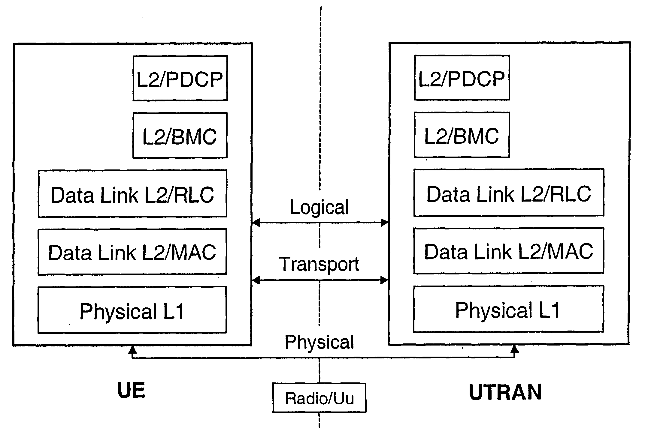
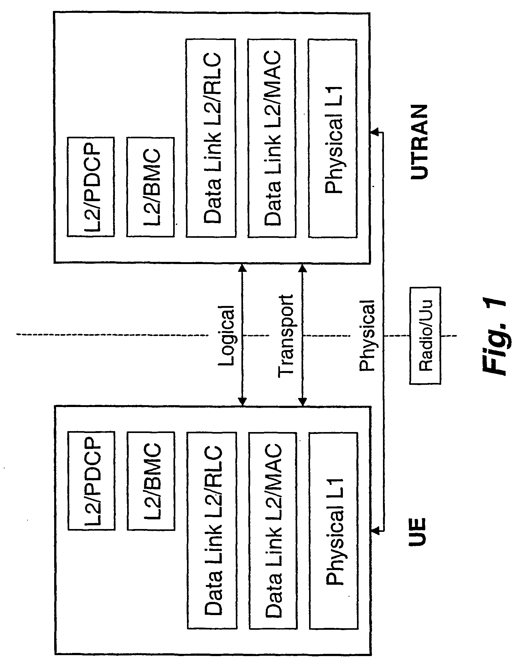
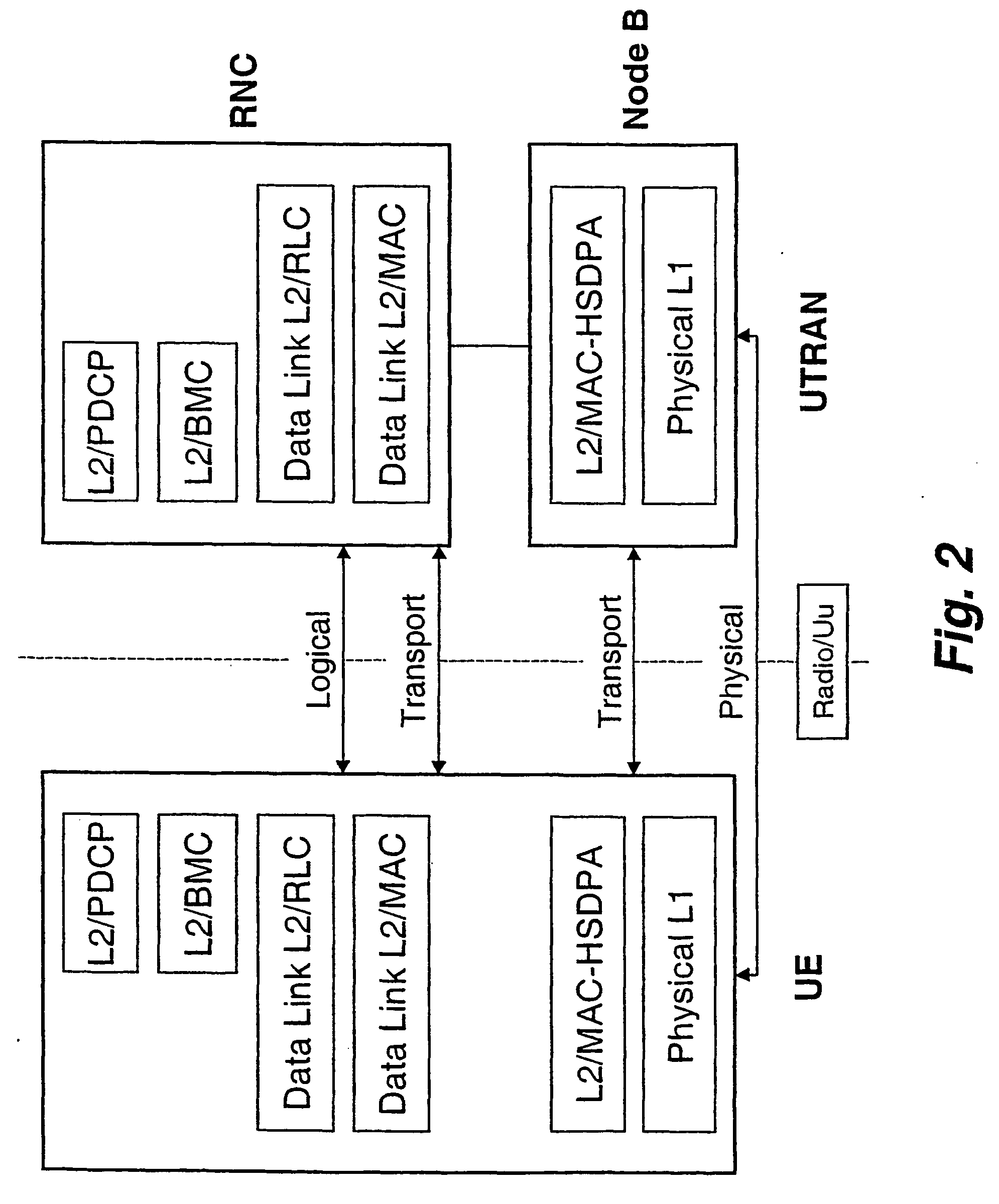
[0046] FIG. 2 show a preferred layered protocol structure, a protocol stack, according to the invention The L2 MAC layer of FIG. 1 has been extended and divided into two sub-layers, a new L2 MAC sub-layer and a new MAC-HSDPA sub-layer. Essentially the new L2 MAC sub-layer corresponds to the prior art L2 MAC sub-layer of FIG. 1. The MAC-HSDPA plus the MAC layer could be regarded as one single MAC layer extended to also include hybrid ARQ functionality. However, for reasons of explanation they are preferably regarded as separate sub-layers. Further, on the network side, considering them as separate protocol sub-layers physically better corresponds to the physical entities where they reside. As illustrated in FIG. 2 on the UTRAN-side (or network side) L2 MAC sub-layer is preferably located in RNC, whereas L2 MAC-HSDPA sub-layer is located in Node B. As the hybrid ARQ protocol combines successively received retransmissions it is a great advantage to have this protocol close to the physi...


PUM


Abstract

The present invention relates to gen-eration and transmis-sion of status reports utilizing available HARQ infor-ma-tion. The invention is well suited for a cellu-lar mo-bile radio communications sys-tem, particularly a Universal Mobile Telecommunications System, UMTS.

Description

[0001] The present invention relates to retransmissions in a communications system, and more especially it relates to a cellular mobile radio system, particularly to a Universal Mobile Telecommunications System, UMTS or WCDMA system.BACKGROUND AND DESCRIPTION OF RELATED ART[0002] Retransmission of data to or from a mobile station, MS, or user equipment, UE, is previously known. It is also known to use medium access control and radio link control layers of a UMTS protocol structure in acknowledged mode for dedicated channels.[0003] In acknowledged mode, retransmissions are undertaken in case of detected transmission errors not recovered by forward error control. This is also called automatic repeat request, ARQ. With ARQ, retransmissions can be undertaken unless a transmitted message is (positively) acknowledged or if it is negatively acknowledged. Generally there are time limits for the respective positive and negative acknowledgements to be considered.[0004] Within this patent appl...

Claims


Application Information

Patent Timeline
Patent Type & Authority Applications(United States)
IPC IPC(8): H04L1/16H04L1/18H04L12/24H04L12/56H04W28/04H04W84/04
CPCH04L1/1628H04L1/1812H04W84/04H04L41/06H04W28/04H04L1/1848
Inventor PARKVALL, STEFANTORSNER, JOHAN
Owner TELEFON AB LM ERICSSON (PUBL)
Why Eureka
Try Eureka