Combustion chamber arrangement

a combustion chamber and combustion chamber technology, applied in mechanical equipment, machines/engines, lighting and heating apparatus, etc., can solve the problems of low cooling efficiency, reduced cooling effect, and reduced cooling efficiency of very small area cooled in quasi-closed manner, so as to achieve simple structure and significant improvement of cooling efficiency

a combustion chamber and combustion chamber technology, applied in mechanical equipment, machines/engines, lighting and heating apparatus, etc., can solve the problems of low cooling efficiency, reduced cooling effect, and reduced cooling efficiency of very small area cooled in quasi-closed manner, so as to achieve simple structure and significant improvement of cooling efficiency

US20040237500A1Inactive Publication Date: 2004-12-02SIEMENS AG

Image

  • Combustion chamber arrangement
  • Combustion chamber arrangement
  • Combustion chamber arrangement

Examples


Embodiment Construction

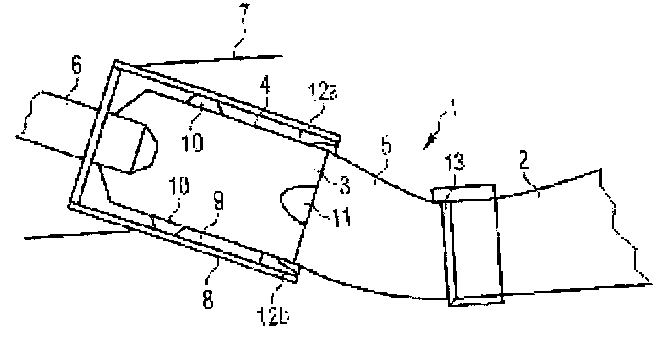
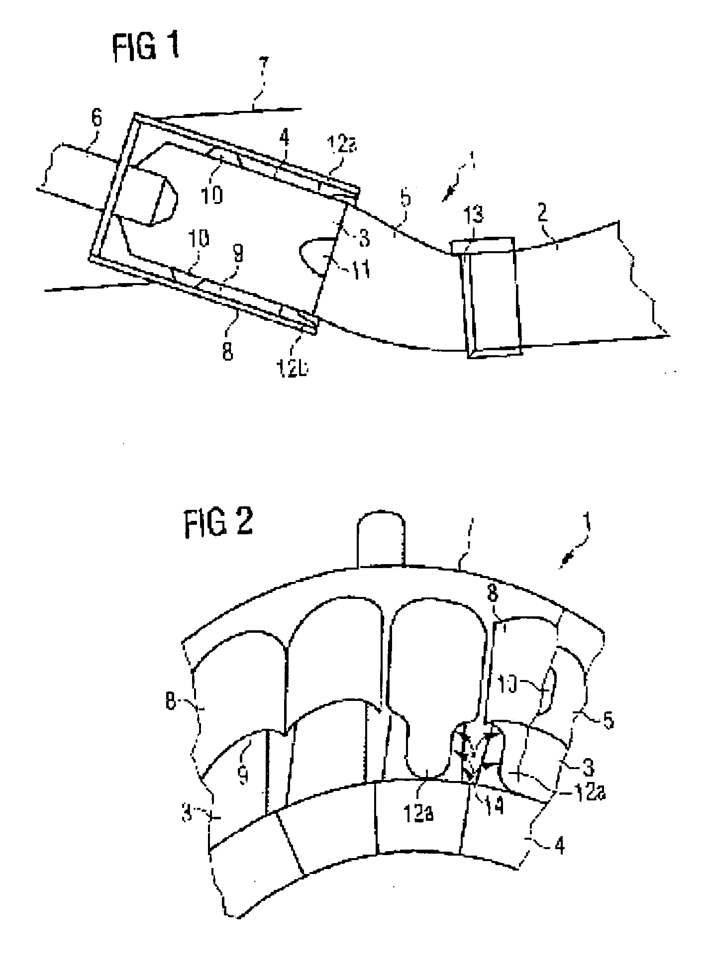
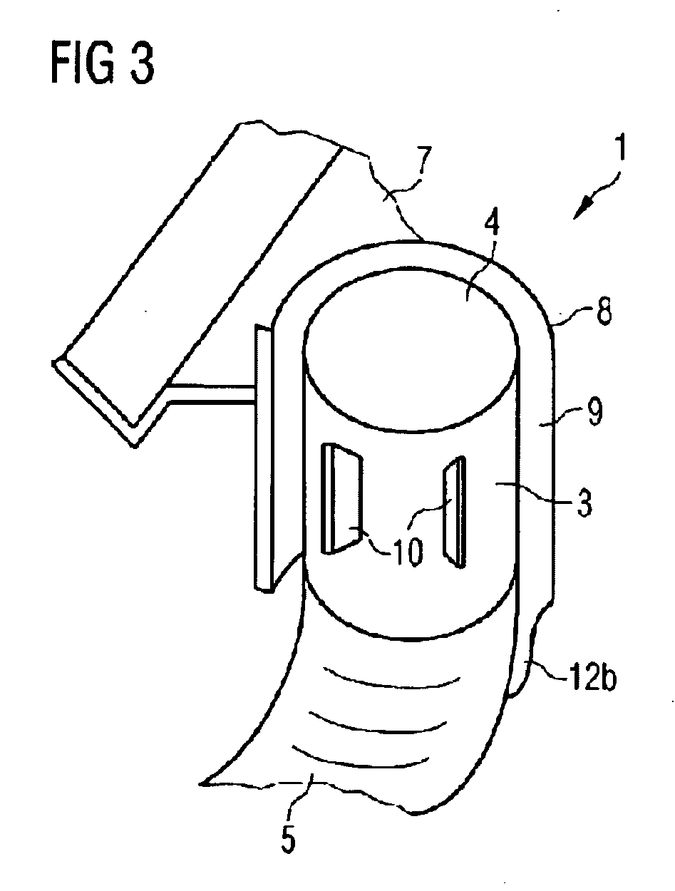
[0021] FIG. 1 shows a cross-sectional view of a section from a gas turbine with a combustion chamber arrangement 1 according to the invention. The combustion chamber arrangement 1 comprises a plurality of individual combustion chambers 3, which are arranged in an overlapping ring shape and open into a common annular gap 13. The annular gap 13 in turn opens into a turbine chamber 2 in which schematically indicated vanes and blades of the turbine are located.

[0022] Burners 6 are arranged ahead of each of the individual combustion chambers 3. These are used to ignite a mixture comprising an oxygenous fuel gas and a propellant, said mixture continuing to burn in the individual combustion chambers 3. The individual combustion chambers 3 thereby comprise an inlet section 4 attached to the burner 6 and a transition section 5 transitioning the inlet section 4 in the direction of the annular gap 13. The burners 6 are connected to the individual combustion chambers 3 through a turbine outer h...


PUM


Abstract

This invention relates to a combustion chamber arrangement for a gas turbine, with a number of individual combustion chambers which open into an annular gap, leading to a turbine chamber, whereby burners are arranged before the individual combustion chambers, connected to the individual combustion chambers through a turbine housing. According to the invention, said combustion chamber arrangement may be further developed, such that the cooling efficiency of the individual combustion chambers may be significantly improved, with an embodiment of simple construction, whereby at least one collar, arranged on one side of the turbine housing, facing the turbine chamber, running radially in the direction of the turbine chamber, at least partly surrounds a section of at least one individual combustion chamber whilst leaving a gap space.

Description

[0001] This application is the US National Stage of International Application No. PCT / EP02 / 09556, filed Aug. 27, 2002 and claims the benefit thereof. The International Application claims the benefits of European application No. 01121089.5 EP filed Sep. 3, 2001, both of the applications are incorporated by reference herein in their entirety.[0002] The invention relates to a combustion chamber arrangement for a gas turbine with a plurality of individual combustion chambers which open into a common annular gap leading to a turbine chamber, whereby burners are arranged ahead of the individual combustion chambers, said burners being connected to the individual combustion chambers through an outer housing. The invention also relates to a gas turbine with such a combustion chamber arrangement.BACKGROUND OF INVENTION[0003] Combustion chamber arrangements of this kind for gas turbines are known in the prior art. A mixture of an oxygenous fuel gas and a propellant is ignited in the burners an...

Claims


Application Information

Patent Timeline
02 Dec 2004
Publication
US20040237500A1
IPC
F23R3/42; F01D25/14; F02C7/18; F23R3/00; F23R3/46; F23R3/54; F23R3/60
CPC
F01D25/14; F23R3/002; F23R3/46; F23R3/60
Inventors
TIEMANN, PETER