Storage system and setting method for storage configuration information

a storage system and information technology, applied in the field of storage system and setting method for storage configuration information, can solve the problems of difficult and time-consuming operation of setting or changing storage configuration information via a network, and the difficulty of setting and changing storage configuration information is difficult and time-consuming operation, so as to achieve the effect of smoothly setting storage configuration information

Inactive Publication Date: 2005-01-27
HITACHI LTD
View PDF8 Cites 33 Cited by
  • Summary
  • Abstract
  • Description
  • Claims
  • Application Information

AI Technical Summary

Benefits of technology

[0008] One embodiment of the present invention is directed to provide a storage system and a setting method for storage configuration information that can set the storage configuration information smoothly.
[0009] Another embodiment of the present invention is directed to provide a storage system and a setting method for storage configuration information that provide for easy centralized management of copy pair volumes dispersed on a network by conducting a series of operations from a management computer.

Problems solved by technology

It is, thus, sometimes necessary to change the configuration of a storage system in response to occasional request, but even if a management server has been provided, setting or changing the storage configuration information via a network is a difficult and time-consuming operation.
As a result, setting and changing the storage configuration information is a difficult and time-consuming operation.

Method used


Image

  • Storage system and setting method for storage configuration information
  • Storage system and setting method for storage configuration information
  • Storage system and setting method for storage configuration information

Examples


first embodiment

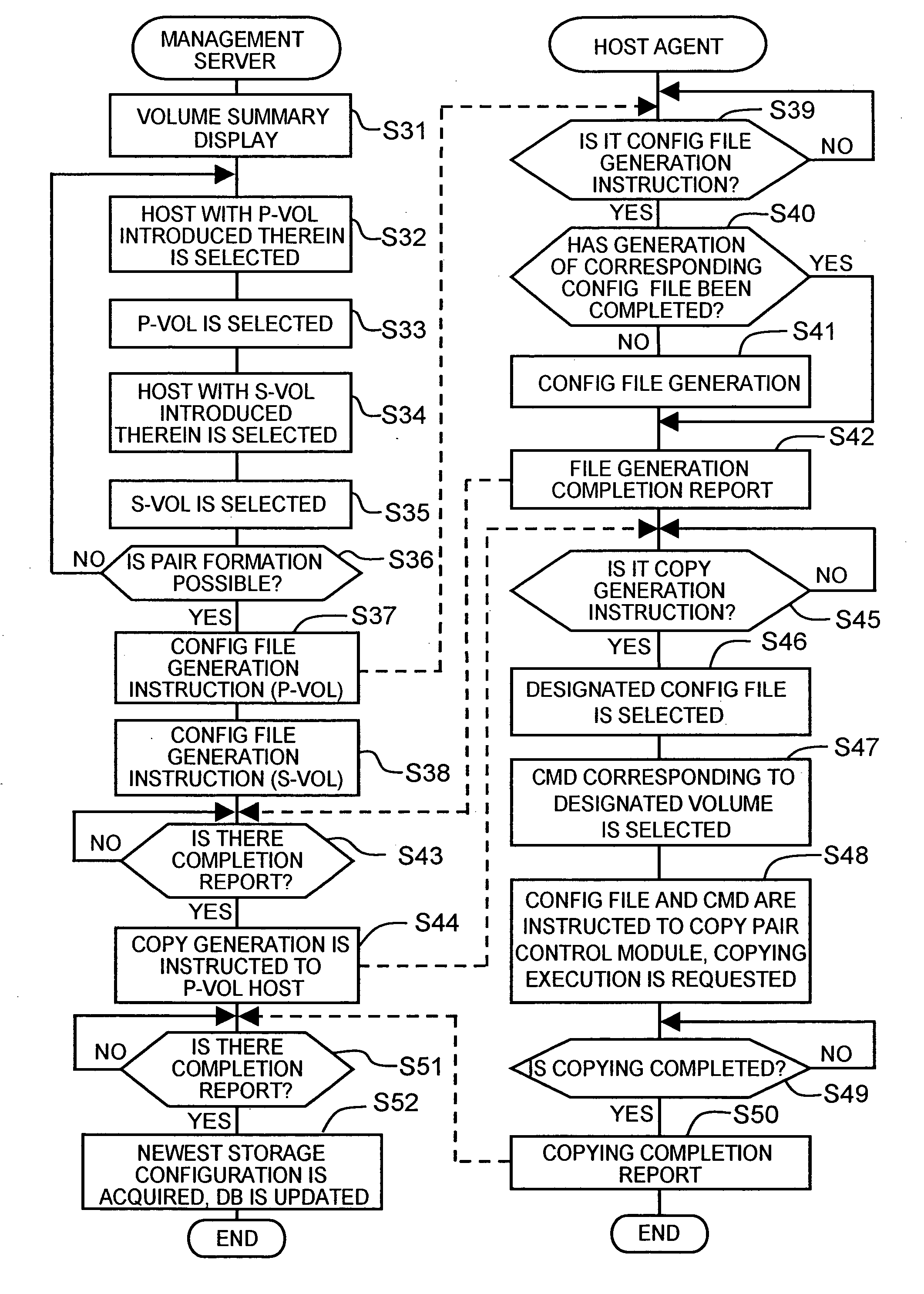
[0048] [First Embodiment]

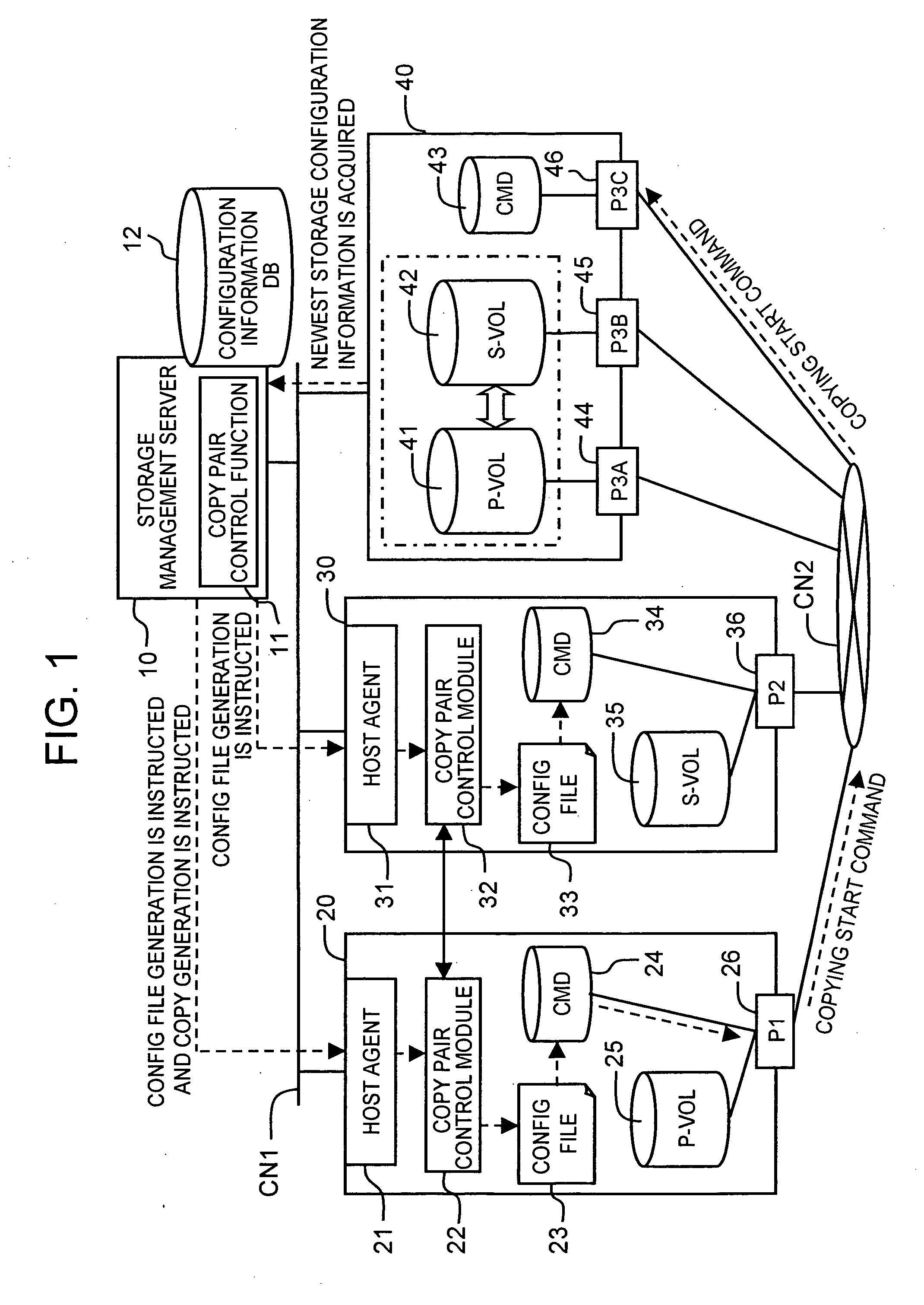
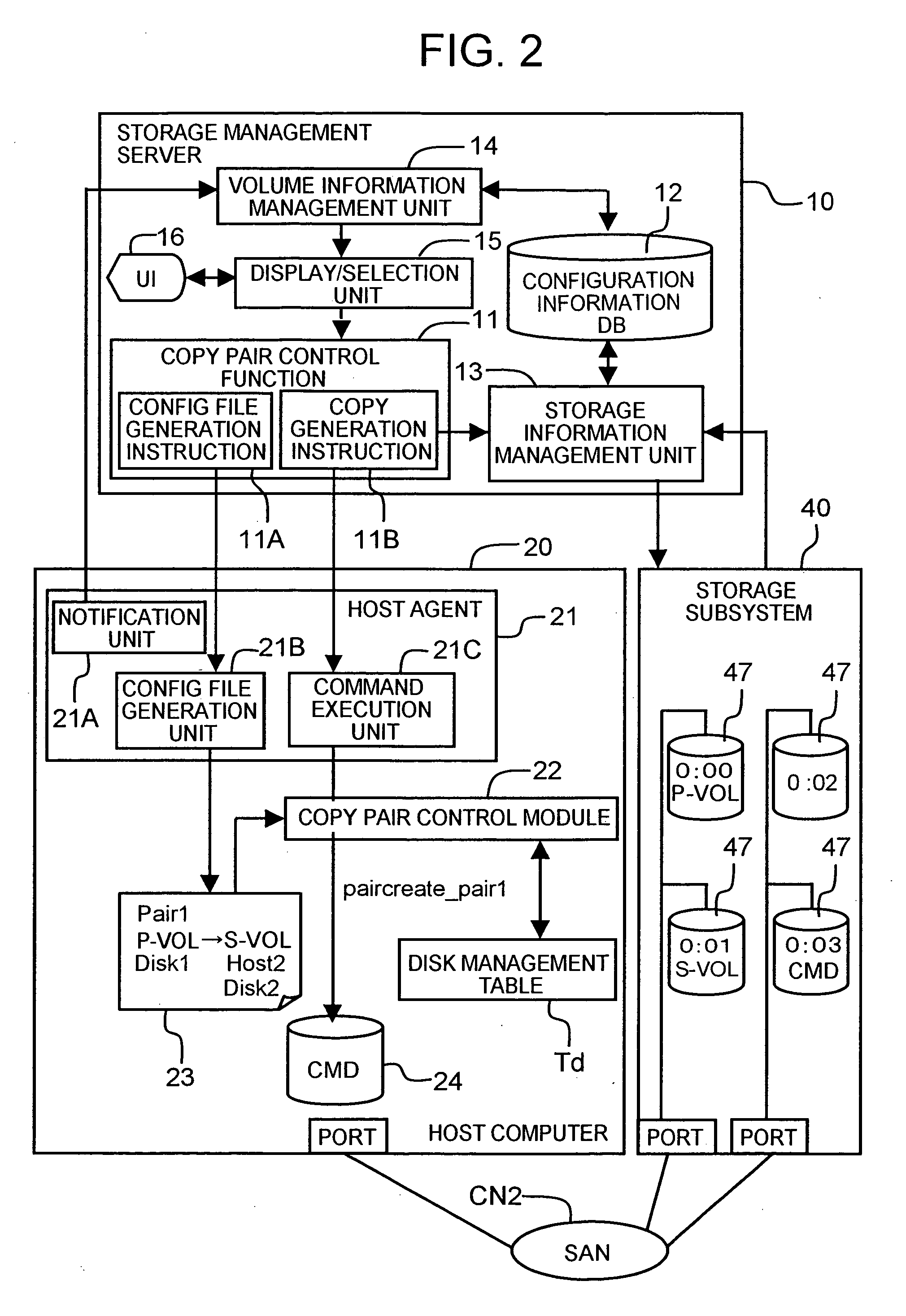
[0049] The first embodiment of the present invention will be described below based on FIGS. 1 through 7. FIG. 1 is a block diagram showing the outline of the entire storage system of the present embodiment.

[0050] The storage system comprises a storage management server 10, a plurality of host computers 20, 30, a storage subsystem 40, and a first communication network CN1 and a second communication network CN2 for connecting those devices, each of the aforesaid components being described hereinbelow.

[0051] The storage management server (abbreviated hereinbelow as “a management server”) 10 serves for managing the storage subsystem 40. The management server 10 comprises a copy pair control function 11 and a configuration information database (abbreviated hereinbelow as DB) 12. The management server 10 instructs the generation of a configuration setting file (shown as a “config file” in the figures) to the host computers 20, 30 and instructs the host computer ...

second embodiment

[0085] [Second Embodiment]

[0086] The second embodiment of the present invention will be explained hereinbelow with reference to FIGS. 8 through 11. The specific feature of the present embodiment is that the notification of the copying start instruction has been optimized.

[0087]FIG. 8 shows the outline of the entire storage system of the present embodiment. For example, three host computers 50, 60, 70 are provided in the storage subsystem of the present embodiment. The host computers 50, 60, 70 comprise the respective host agents 51, 61, 71, copy pair control modules 52, 62, 72, configuration setting files 53, 63, 73, control devices 54, 64, 74, and volumes. The first host computer 50 comprises a primary volume 55. The second host computer 60 comprises a secondary volume 65 forming a pair with the primary volume 55 of the first host computer 50 and the other primary volume 66. The third host computer 70 has a secondary volume 75 forming a pair with the primary volume 66 of the secon...

third embodiment

[0098] [Third Embodiment]

[0099]FIG. 12 is a block diagram showing the outline of the entire storage system of the third embodiment of the present invention. A specific feature of the present embodiment is the application to the case in which copy pairs are formed by a plurality of storage subsystems.

[0100] The storage subsystem of the present embodiment comprises a first storage subsystem 90 and a second storage subsystem 100. The first storage subsystem 90 provides a primary volume 91 to the first host computer 20. The second storage subsystem 100 provides a secondary volume 101 to the second host computer 30. The storage subsystems 90, 100 comprises respective control devices 92, 102. The primary volume 91 of the first storage subsystem 90 and the secondary volume 101 of the second storage subsystem 100 form a copy pair.

[0101] A copy command from the host computer 20 is transmitted to the control devices 92, 102 of respective storage subsystems 90, 100. Furthermore, if the copyi...


PUM


Abstract

Pairs are formed from a plurality of dispersed volumes and copying between the volumes is conducted by a series of remote operations from a management server. A management server 10 instructs the generation of configuration setting files 23, 30 to host computers 20, 30 selected so as to form copy pairs. If the configuration setting files are generated by host agents 21, 31, the management server 10 instructs copy start to a host computer 20 having a primary volume. The host agent 21 generates a prescribed command via a copy pair control module 22 and causes a storage subsystem 40 to execute copying between the volumes. When copying is completed, the management server 10 acquires the newest storage configuration information from the storage subsystem 40 and updates configuration information DB12.

Description

CROSS-REFERENCE TO RELATED APPLICATIONS [0001] This application relates to and claims priority from Japanese Patent Application No. 2003-278737 filed on Jul. 24, 2003, the entire disclosure of which is incorporated herein by reference. BACKGROUND OF THE INVENTION [0002] 1. Field of the Invention [0003] The present invention relates to a storage system in which, for example, a storage device such as a disk array subsystem and a host computer are connected via a communication network and to a setting method for storage configuration information. [0004] 2. Description of the Related Art [0005] In database systems handling large-scale data, such as data center, data are managed by using storage subsystems such as disk array devices. Because the disk array devices are configured by arranging a multiplicity of disks in an array-like pattern, they are created based on, for example, RAID (Redundant Array of Independent Inexpensive Disks). In disk array devices, a logical volume which is a l...

Claims


Application Information

Patent Timeline
Patent Type & Authority Applications(United States)
IPC IPC(8): G06F3/06G06F12/00
CPCG06F3/0605G06F11/2069G06F3/067G06F3/0634
Inventor OHNO, SHOTAROKAWANO, TOSHIHIKOKITAYAMA, TAKASHIHARUMA, TOSHIYUKIONO, AKINORINAGASHIMA, YUICHIRO
Owner HITACHI LTD
Why Eureka
Try Eureka