

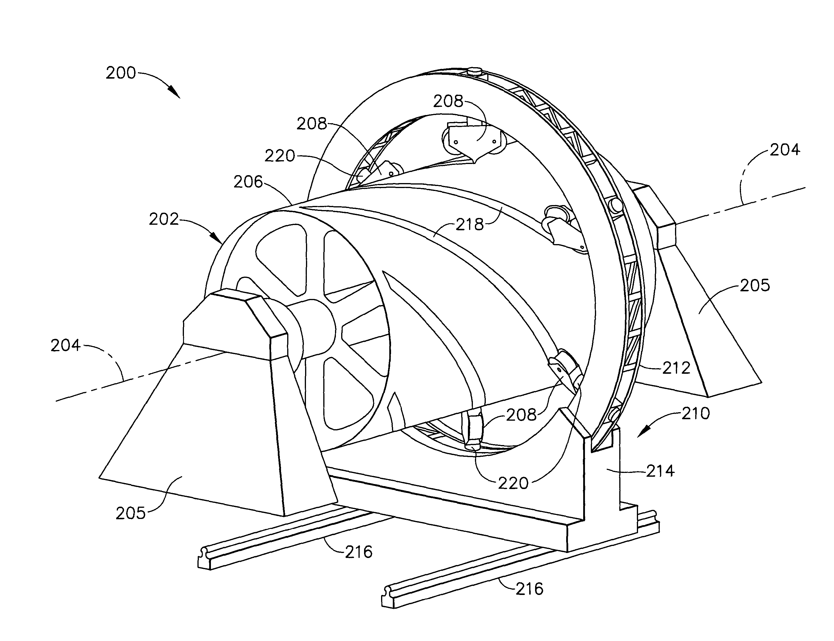
Multiple head automated composite laminating machine for the fabrication of large barrel section components
a composite laminating machine and barrel section technology, applied in the direction of process and machine control, mechanical control devices, instruments, etc., can solve the problems of slow current processes such as tape laying and fiber placement, and achieve the effect of meeting the production rate of new large-scale aircraft programs
- Summary
- Abstract
- Description
- Claims
- Application Information
AI Technical Summary
Benefits of technology
Problems solved by technology
Method used
Image

Examples
Embodiment Construction
[0025] The following detailed description is of the best currently contemplated modes of carrying out the invention. The description is not to be taken in a limiting sense, but is made merely for the purpose of illustrating the general principles of the invention, since the scope of the invention is best defined by the appended claims.
[0026] Broadly, one embodiment of the present invention provides fabrication of large parts, such as fuselage structures, made of composite materials, which may be used, for example, in the manufacture of commercial and military aircraft. In one embodiment, the present invention enables the automated lay down and compaction of large quantities of high performance composite materials onto large (typically greater than 15 feet in diameter, or maximum thickness), constant cross section, rounded-shaped, for example, circular or elliptical cross-section, mandrels at very high rates compared to the prior art. For example, using one embodiment, placement, i....
PUM
| Property | Measurement | Unit |
|---|---|---|
| diameter | aaaaa | aaaaa |
| widths | aaaaa | aaaaa |
| widths | aaaaa | aaaaa |
Abstract
Description
Claims
Application Information