High efficiency aircraft cabin air supply cooling system

a cooling system and high-efficiency technology, applied in the field of high-efficiency aircraft cabin air supply cooling system, can solve the problems of imposing the burden of compressing the outside, consuming enormous amounts of energy, and requiring a significant amount of energy to bring outside, so as to reduce the need for make-up air

a cooling system and high-efficiency technology, applied in the field of high-efficiency aircraft cabin air supply cooling system, can solve the problems of imposing the burden of compressing the outside, consuming enormous amounts of energy, and requiring a significant amount of energy to bring outside, so as to reduce the need for make-up air

US20050051668A1Active Publication Date: 2005-03-10THE BOEING CO

Image

  • High efficiency aircraft cabin air supply cooling system
  • High efficiency aircraft cabin air supply cooling system
  • High efficiency aircraft cabin air supply cooling system

Examples


Embodiment Construction

[0035] The following description of the preferred embodiment(s) is merely exemplary in nature and is in no way intended to limit the invention, its application, or uses.

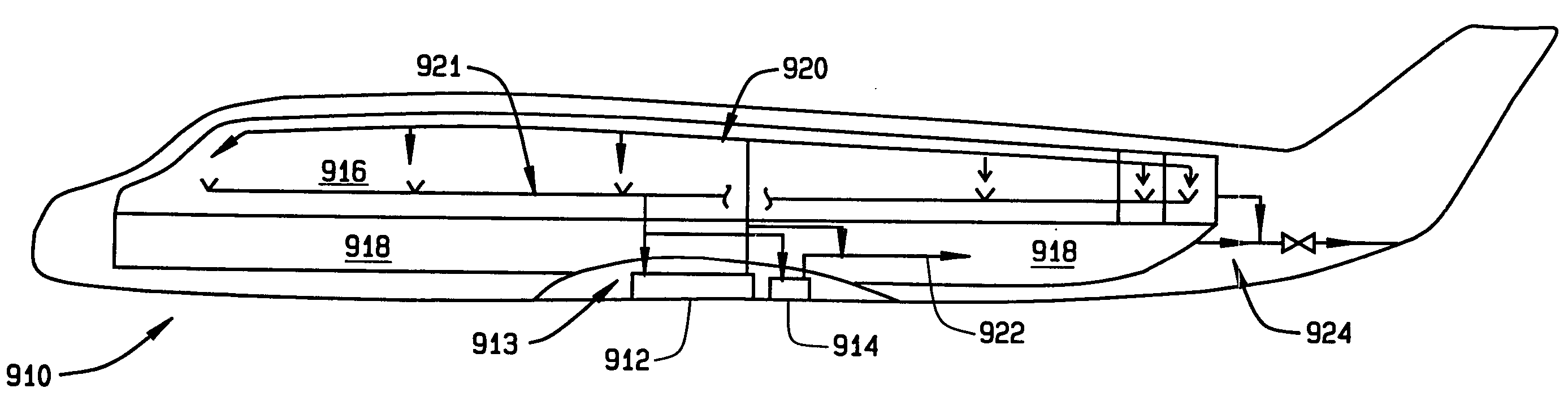
[0036] As noted, modern aircraft use conditioned outside air for many different purposes within the pressurized volume of the aircraft. Some examples of these uses include: [0037] a) Cabin, flight deck, crew rest, lavatory, and galley ventilation and temperature control for crew and passengers [0038] b) Flow to clear smoke from the flight deck [0039] c) Flow to prevent lower lobe smoke from penetrating into the cabin or flight deck [0040] d) Cargo compartment ventilation and temperature control for animals and perishables [0041] e) Equipment cooling

[0042] While the prior art treated these air conditioning needs without regard to whether the need represents a ventilation need or a temperature control need, the present invention makes the difference between these types of needs explicit. Generally, air conditioning e...


PUM


Abstract

A thermal management system for an aircraft is provided. The aircraft includes a primary air conditioning system which compresses and cools outside air to create inside air. The inside air pressurizes the internal volume of the aircraft and ventilates a first object in the internal volume. An exhaust exhausts a portion of the inside air to allow more outside air to be drawn into the aircraft. A cooler cools a coolant which in turn controls temperature of at least two objects in the internal volume.

Description

FIELD OF THE INVENTION [0001] The present invention relates to a system to efficiently condition air to be supplied to the interior of an aircraft, and more particularly to a system to save energy by reducing the need for outside air. [0002] BACKGROUND OF THE INVENTION [0003] It is necessary on large, modern aircraft to ventilate the interior of the aircraft and to provide temperature control. Some examples of these uses include: [0004] a) Cabin, flight deck, crew rest, lavatory, and galley ventilation and temperature control for crew and passengers [0005] b) Flow to clear smoke from the flight deck [0006] c) Flow to prevent lower lobe smoke from penetrating into the cabin or flight deck [0007] d) Cargo compartment ventilation and temperature control for animals and perishables [0008] e) Equipment cooling [0009] Traditionally, outside air (also known as pack air or conditioned air) has been the primary means of meeting the various aircraft air conditioning requirements. From the out...

Claims


Application Information

Patent Timeline
10 Mar 2005
Publication
US20050051668A1
IPC
B64D13/06
CPC
B64D13/06; B64D2013/0614; Y02T50/56; B64D2013/0674; Y02T50/44; B64D2013/0629; Y02T50/40; Y02T50/50
Inventors
ATKEY, WARREN A.; FITERMAN, CHARLES J.