Dual-band lens

a dual-band, lens technology, applied in the field of optics, can solve the problems of cost and difficulty of manufacture, both approaches, and the need for a larger beam-splitting devi

Active Publication Date: 2005-03-10
CBC AMERICA
View PDF12 Cites 32 Cited by
  • Summary
  • Abstract
  • Description
  • Claims
  • Application Information

AI Technical Summary

Problems solved by technology

However, there are problems with both approaches.
However, as aperture increases, a larger and larger beam-splitter is required.
As beam-splitter size increases, so does cost and difficulty of manufacture.
Further, if the two cameras have adjustable focus or zoom, matching focus or zoom changes between the two separate systems can be difficult.
This could make it

Method used


Image

  • Dual-band lens
  • Dual-band lens
  • Dual-band lens

Examples


Embodiment Construction

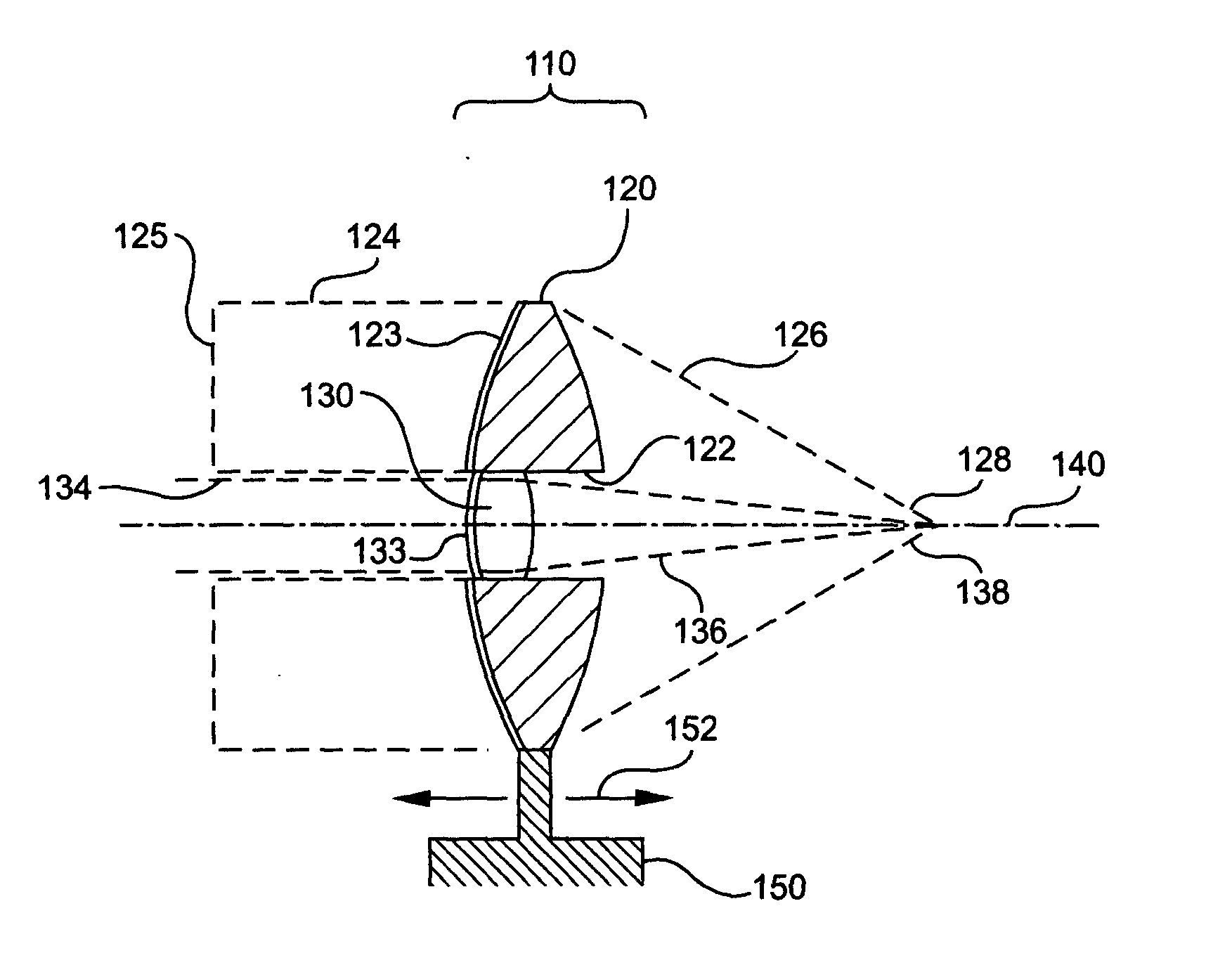
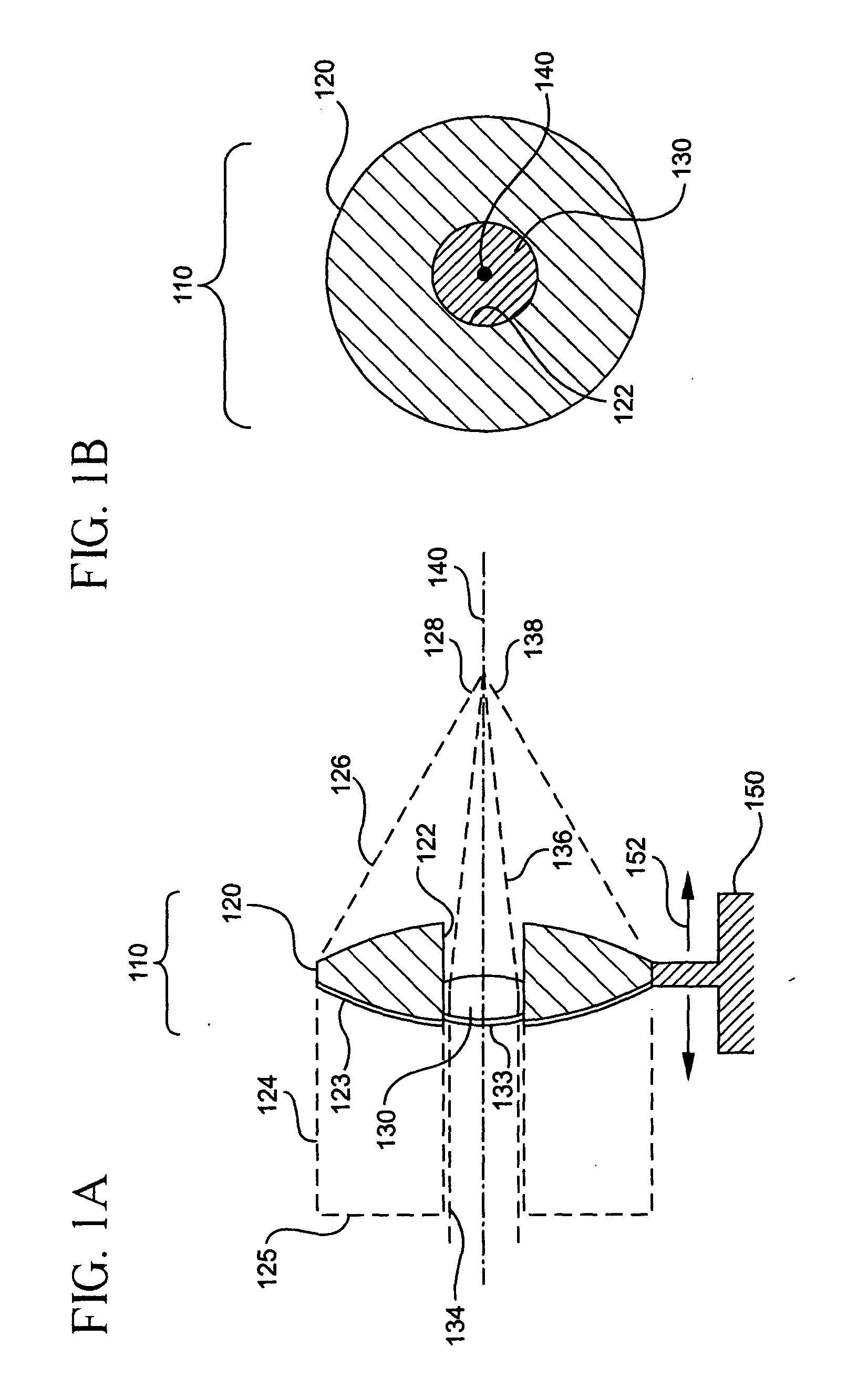
[0011]FIG. 1A and FIG. 1B are plan and axial views of a single dual-band lens, according to the present invention.

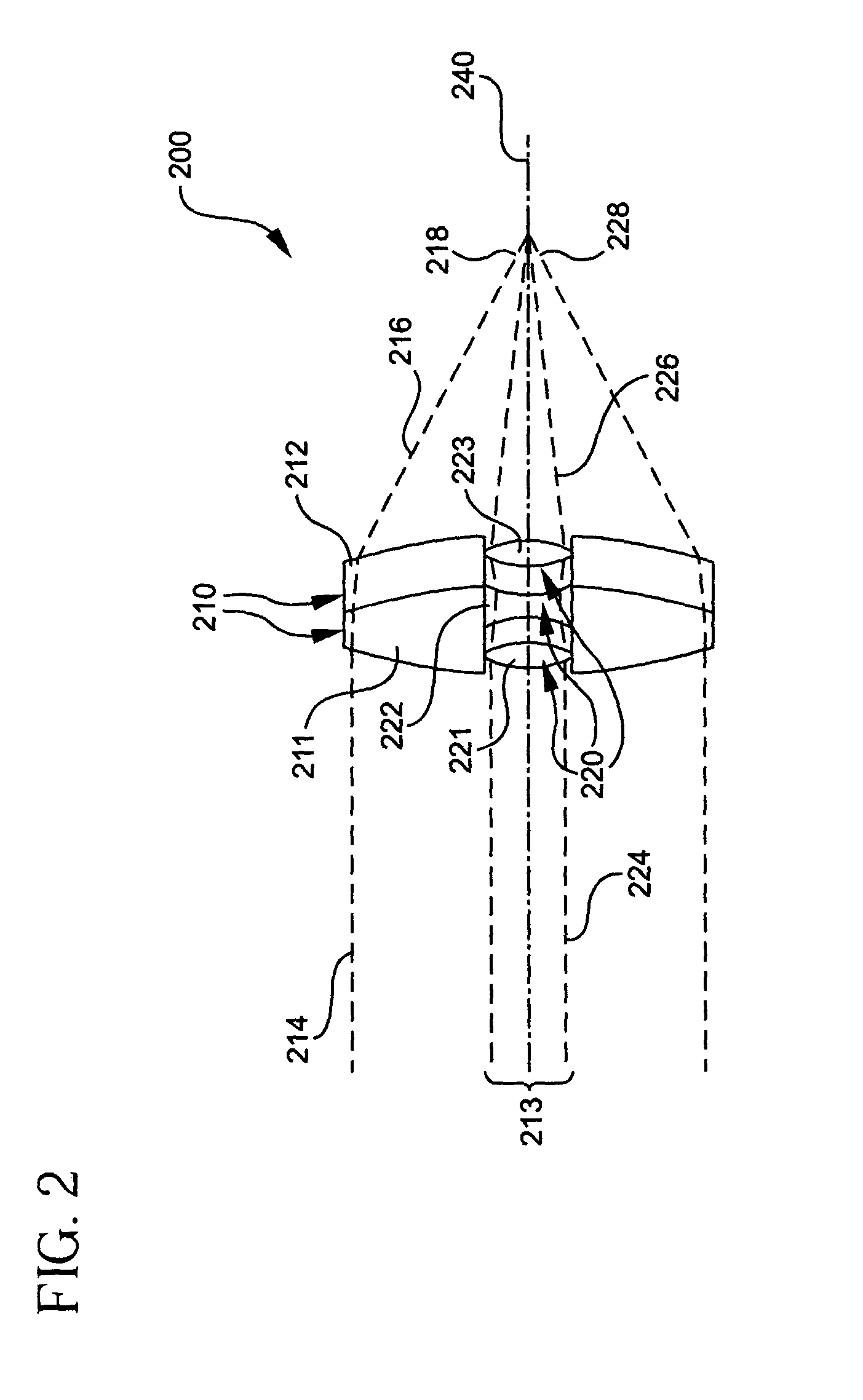
[0012]FIG. 2 is a plan view of a complex dual-band lens, according to the present invention.

[0013]FIG. 3 is a plan view of a dual band lens with a focus group, according to the present invention.

[0014]FIG. 4A is a plan view of a dual band zoom lens, according to the present invention.

[0015]FIG. 4B-FIG. 4I are diagrams that illustrate the motions of infrared and visible subsystems in a dual band lens, according to the present invention.

[0016]FIG. 5 is a plan view of a dual wavelength camera, according to the present invention.

DESCRIPTION

[0017]FIG. 1A and FIG. 1B are plan and axial views of a single dual-band lens, according to the present invention. The dual bands may be any optical bands (e.g., near-infrared, mid-infrared, long-infrared, very-long-infrared, visible, ultraviolet). Dual-band lens 110 is formed of first lens element 120, which is constructed of a refr...


PUM


Abstract

A single lens or optical system is used to image two different optical bands, for example visible and infrared, with the same possible adjustments in zoom and/or focus. A dual band singlet is formed of a first, larger, optical element, suitable for operating on light of a first optical band, with an aperture cut out of it. A smaller element, suitable for operating on light of a second optical band, is secured in, or on either side of, the aperture cut through the larger optical element, thus forming a dual band singlet that can operate on two different wavelength bands. Combinations of dual band lenses, lens elements, and lenses with cut-out apertures are used to form dual-band optical systems, including systems with dual-band focus and zoom.

Description

FIELD OF THE INVENTION [0001] 1. Field [0002] Embodiments relate to the field of optics and in particular to imaging lenses. [0003] 2. Related Art [0004] Different cameras, sensitive to different optical wavelength bands, are commercially available for a variety of applications. For example, visible cameras and infrared cameras are used in industrial, security, and rescue applications. Infrared and Ultraviolet cameras are used in fire detection. It can be advantageous to have two different cameras, sensitive to two different wavelength bands, observe the same scene. For example, a visible camera could be combined with an infrared camera. The visible camera would show a typical image of a scene, so that an operator could see normally. Meanwhile, the infrared camera would show the operator where there were hot-spots. [0005] One approach to providing dual waveband viewing is to mount two separate cameras on a common base. Another approach is to use a shared reflective optical system, b...

Claims


Application Information

Patent Timeline
IPC IPC(8): G02B13/14G02B15/00
CPCG02B3/10G02B15/00G02B13/146
Inventor LAWSON, JOHNTER LOUW, JAN DAVID
Owner CBC AMERICA
Why Eureka
Try Eureka