

Tape creating apparatus
- Summary
- Abstract
- Description
- Claims
- Application Information
AI Technical Summary
Benefits of technology
Problems solved by technology
Method used
Image

Examples
Embodiment Construction
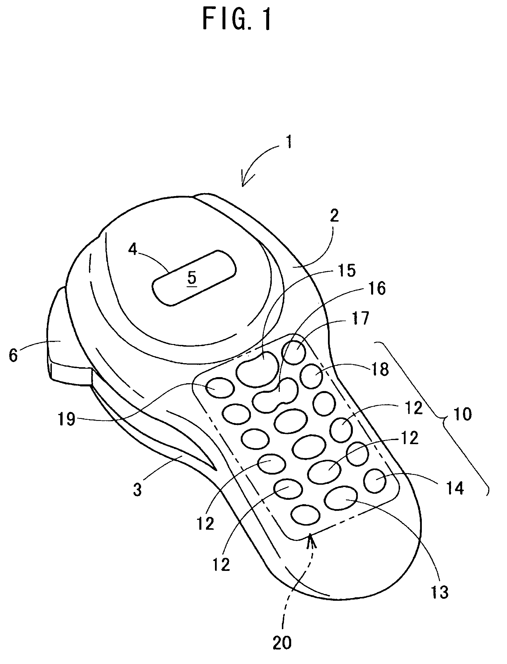
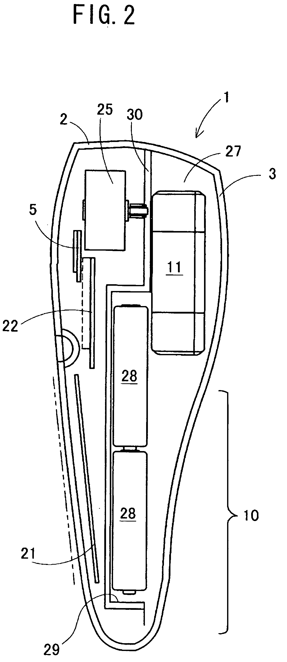
[0043] The tape creating apparatus according to the invention will now be explained in detail on the basis of an embodiment in which the invention has been embodied while referring to the drawings. A schematic structure of the tape creating apparatus according to the embodiment will first be explained on the basis of FIGS. 1 and 2. FIG. 1 is a schematic perspective view of an external appearance of the tape creating apparatus according to an exemplary embodiment of the invention, and FIG. 2 is a schematic sectional view of the tape creating apparatus according to an exemplary embodiment of the invention.
[0044] As illustrated in FIGS. 1 and 2, the tape creating apparatus 1 is comprised of a main body 2 made of synthetic resin, and a rear cover 3 made of synthetic a resin. The rear cover 3 is attached in a freely attachable / detachable manner so as to cover the entire rear surface portion of the main body 2 (surface opposite to a surface that opposes a user when the tape creating appa...
PUM
 Abstract
Description
Claims
Application Information