Ink tank and ink jet printer

Inactive Publication Date: 2006-03-14
CANON KK
View PDF7 Cites 3 Cited by
  • Summary
  • Abstract
  • Description
  • Claims
  • Application Information

AI Technical Summary

Benefits of technology

[0011]In accordance with the invention hereof, there are provided the ink lead-out portion and the electrode inlet portion, which are connected through a conductive member. Therefore, even if no ink exists, it is possible to easily discriminate on the printer side the condition wher

Problems solved by technology

However, the unavailability of ink is detected, and when the user replaces ink tanks, the ink tank is removed from the printer for a long time so as to cause the ink lead-out port of the printer to be released to the air outside.
Then, there occurs a fear that ink component is solidified in the ink lead-out port, and the communication of ink

Method used


Image

  • Ink tank and ink jet printer
  • Ink tank and ink jet printer
  • Ink tank and ink jet printer

Examples


Example

(First Embodiment)

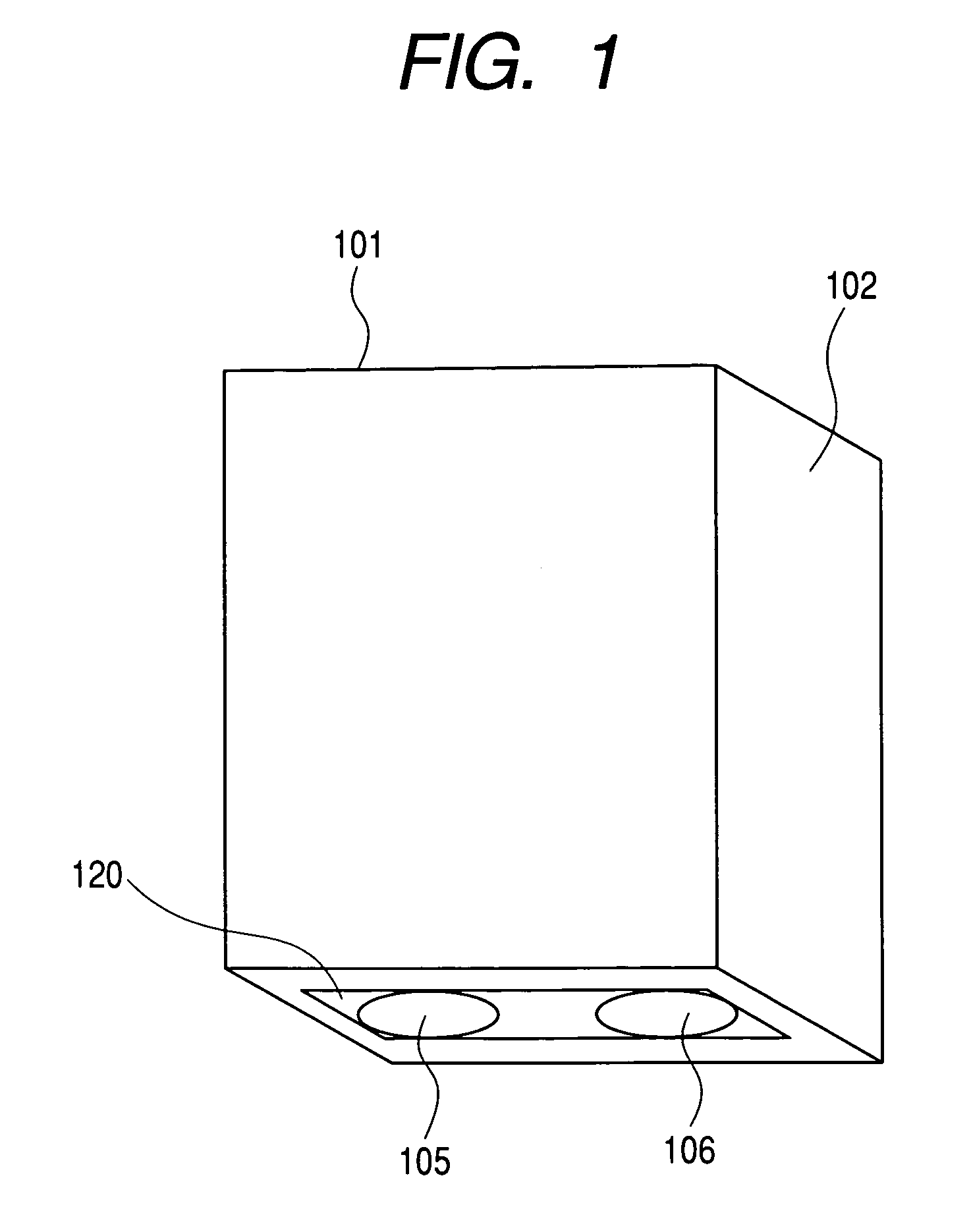
[0022]FIG. 1 is a perspective view that shows one embodiment of an ink tank in accordance with the present invention. The ink tank 101 is provided with an ink tank vessel 102 for containing ink (not shown); an ink lead-out port 105, which is arranged on the bottom face of the ink tank vessel 102 for the ink jet printer that installs this ink tank, and serves as the ink lead-out portion where an ink lead-out needle arranged therefor can be inserted; and an electrode inlet port 106, which serves likewise as the electrode inlet portion where the electrode needle arranged for the ink jet printer can be inserted. At the outset, both the ink lead-out port 105 and the electrode inlet port 106 are airtightly closed or sealed by means of a film 120, which adheres to the ink tank vessel 102. In this manner, it is made possible to prevent ink from leaking to the outside of the ink tank, should ink inside leaks from the ink lead-out port and the electrode inlet port at the tim...

Example

(Second Embodiment)

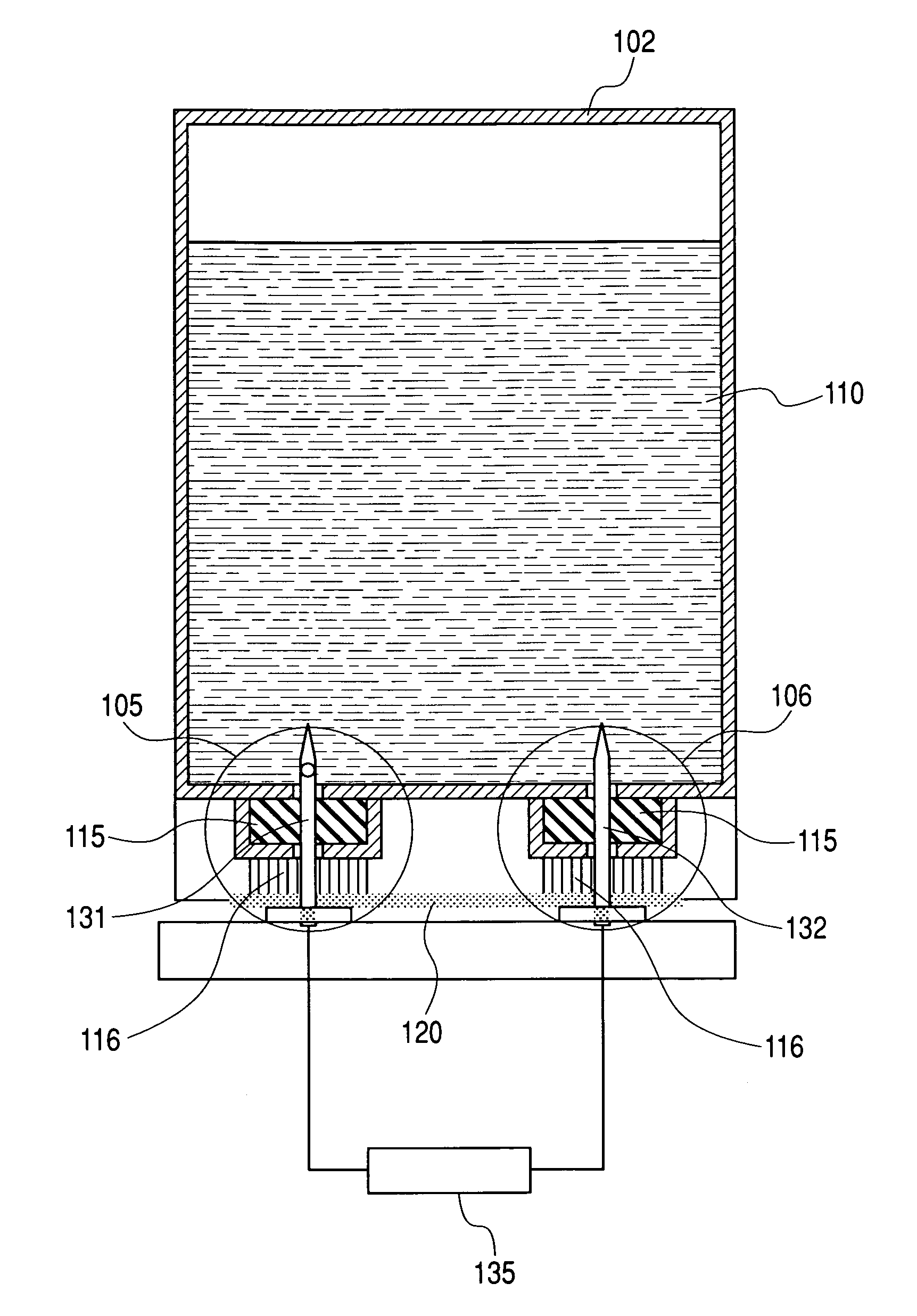
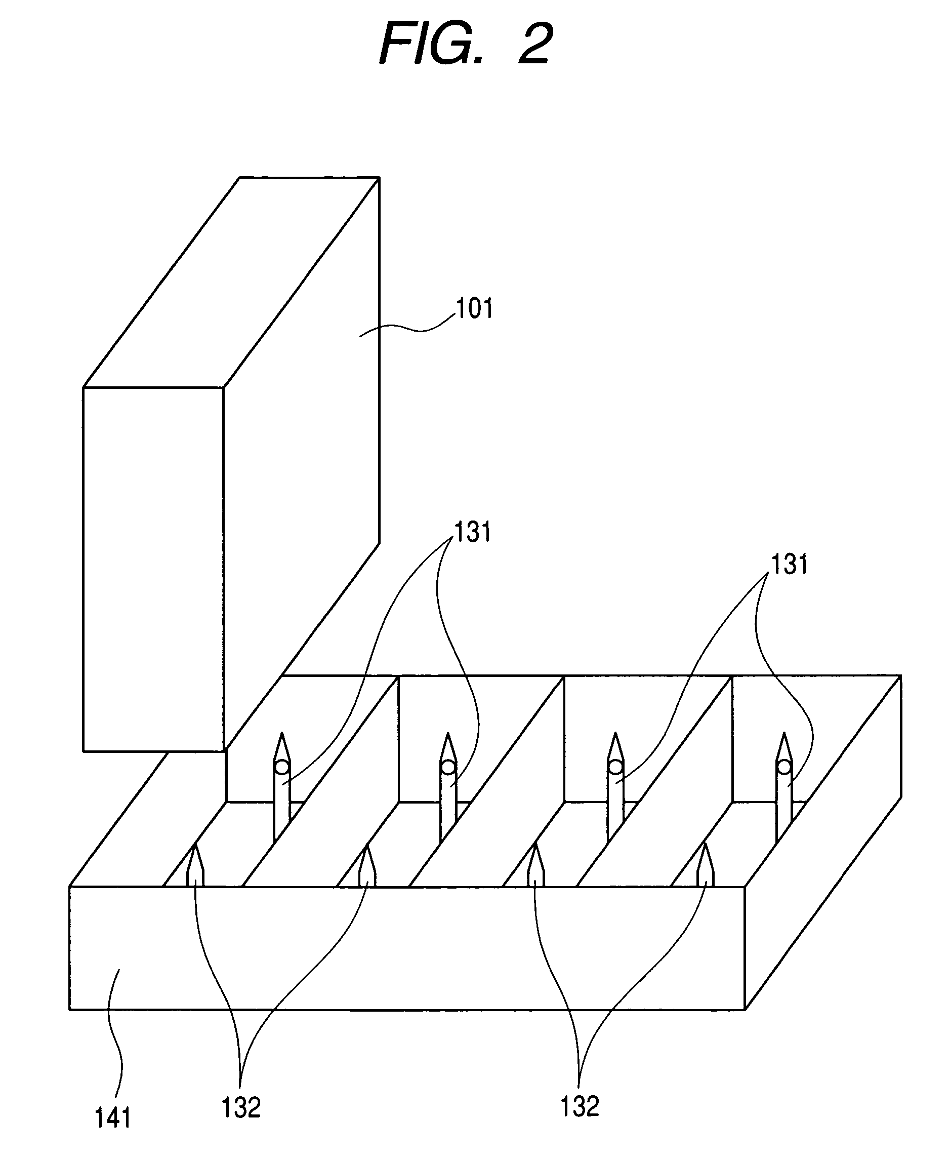
[0034]FIG. 6 is a cross-sectional view that shows the state where the ink tank 101 embodying the present invention is inserted into an ink tank holder 141. There is a fear for the mode of ink tank shown in the first embodiment that if the insertion of the ink tank 101 is repeated for plural times with respect to the ink tank holder 141, the ink lead-out needle and the electrode needle are short-circuited, leading to an erroneous detection, because ink adhering to the needles, ink lead-out port 105, and electrode inlet port 106 is allowed to drop off. Now, therefore, as shown in the present embodiment, both the ink lead-out port 105 and electrode inlet port 106 of the ink tank 101 are sealed with joint rubbers 115. Then, absorbents 116 are arranged below them. The absorbents 116 are held by the film 120 and the ink tank vessel 102. With the structure thus arranged, should any situation occur to allow the dropping off of ink, the absorbents absorb such ink quickly s...

Example

(Third Embodiment)

[0036]There is a fear that the joint rubbers described in conjunction with the first and second embodiments are deteriorated when the ink tank 101 is attached to and detached from the ink tank holder 141 for plural times or the installed condition continues for a long time, and that the sealing capability thereof is lowered. Therefore, in order to secure the durability thereof, it is possible to replace them with the mechanical valve structure as shown in FIG. 7. Each valve is formed by a valve body 117, a valve frame 118, and a spring 119. Usually, the valve body is compressed to the inner wall of the ink tank vessel 102 by the repulsion of the spring. Thus, the opening portions of the ink lead-out port 105 and the electrode inlet port 106 are sealed. When the ink tank 101 is installed on the ink tank holder 141, the ink lead-out needle 131 and the electrode needle 132 push the valve body upward to enable ink and needles to be in contact.

[0037]Here, for this struc...


PUM


Abstract

An ink tank comprises an ink containing portion for containing ink, an ink lead-out portion for leading out ink in said ink containing portion to the outside, and an electrode inlet portion for inletting an electrode into said ink containing portion, said electrode inlet portion being different from said ink lead-out portion, wherein said ink lead-out portion and said electrode inlet portion are connected through a conductive member.

Description

BACKGROUND OF THE INVENTION[0001]1. Field of the Invention[0002]The present invention relates to an ink tank and an ink jet printer. More particularly, the invention relates to an ink jet printer capable of detecting the presence and absence of the ink tank to be installed stationarily in a printer, and the presence and absence of liquid as well. The invention also relates to an ink tank to be used for such printer.[0003]2. Related Background Art[0004]Conventionally, as the ink-availability detection mechanism for an ink tank that contains ink, there has been known the one that measures the electric conductivity between electrodes with the provision of electrodes in an ink tank as disclosed in the specification of Japanese Patent Application Laid-Open No. 06-286160, for example or means for detecting the presence and absence of ink optically.[0005]However, the unavailability of ink is detected, and when the user replaces ink tanks, the ink tank is removed from the printer for a long...

Claims


Application Information

Patent Timeline
IPC IPC(8): B41J29/393B41J2/175
CPCB41J2/17546B41J2/17523
Inventor KITABATAKE, KENJITAKAHASHI, WATARU
Owner CANON KK
Why Eureka
Try Eureka