Three-way pneumatic commutator and volume booster

a commutator and volume technology, applied in the direction of fluid couplings, servomotor components, servomotors, etc., can solve the problems of inability to supply and exhaust a sufficient volume of compressed air to the actuator, inability of pneumatic circuits with large-volume actuators to achieve a quick stroking speed of the piston, and inability of pneumatic circuits operating with large-volume actuators to energize derivative boosters. to achieve the effect of reducing the length of conn

Active Publication Date: 2005-06-02
CONTROL COMPONENTS INC
View PDF3 Cites 12 Cited by
  • Summary
  • Abstract
  • Description
  • Claims
  • Application Information

AI Technical Summary

Benefits of technology

[0020] The integration of the volume boosters, commutators and derivative boosters into pneumatic valving modules advantageously reduces the length of connective piping and fittings included in conventional pneumatic circuits. Such a configuration of the pneumatic valving modules effectively reduces

Problems solved by technology

When a large-volume actuator is utilized in the pneumatic circuit, the positioner, acting alone, may be unable to supply and exhaust a sufficient volume of compressed air to the actuator within a given time period.
Such pneumatic circuits having large-volume actuators may be incapable of achieving a quick stroking speed of the piston.
However, where a low flow rate positioner is utilized, pneumatic circuits operating with large-volume actuators may not be able to energize the derivative booster.
Consequently, they suffer the drawback of a slow stroking speed.
Although it is advantageous to incorporate a lock up feature within a pneumatic circuit, the additional components of the safety valve and the first and second commutators, as shown in FIG. 1B, unfortunately reduce the piston stroking speed.
However, the benefits that are provided by the additional first and second derivative booster

Method used


Image

  • Three-way pneumatic commutator and volume booster
  • Three-way pneumatic commutator and volume booster
  • Three-way pneumatic commutator and volume booster

Examples


first embodiment

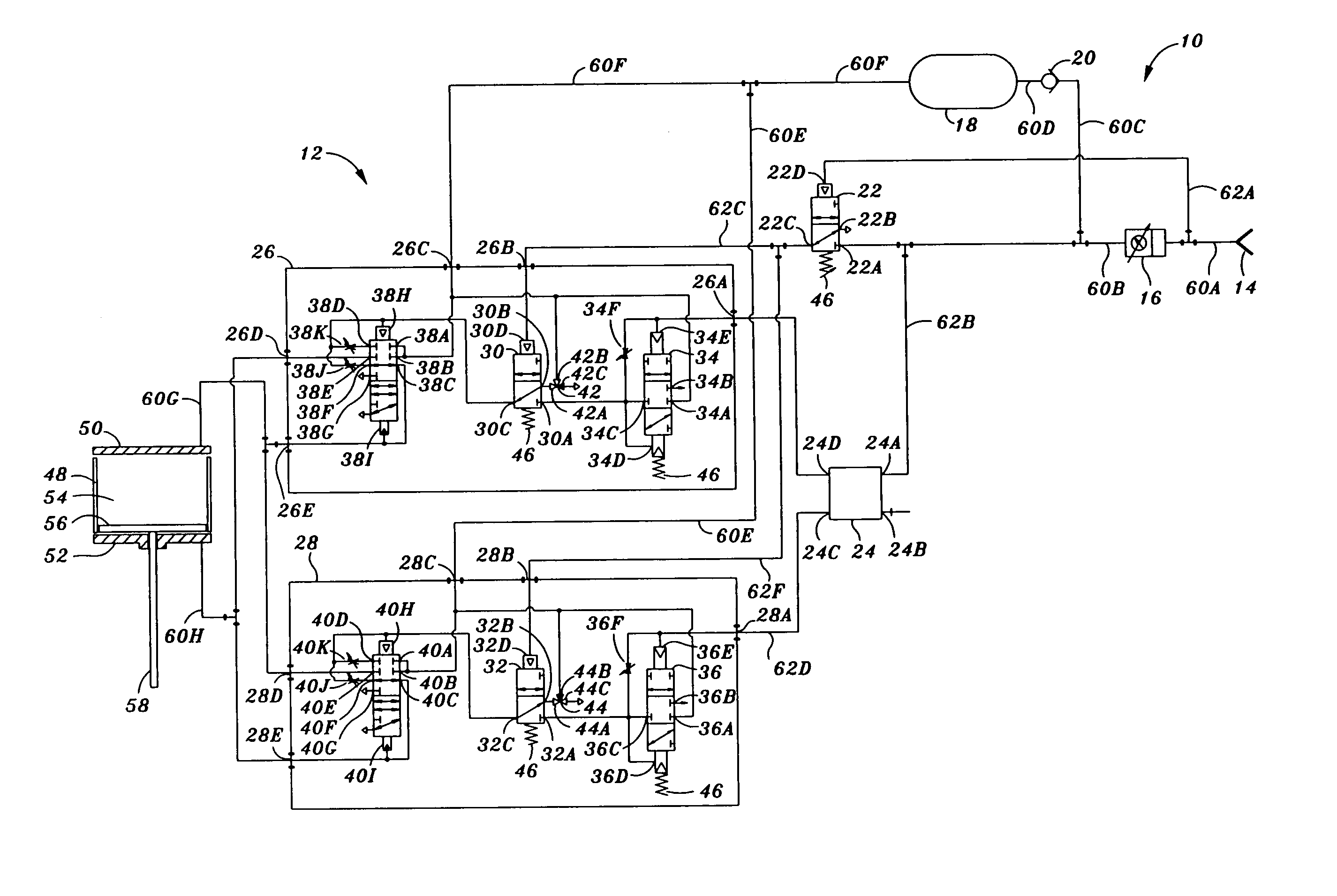
[0053] In the pneumatic circuit 12 of FIG. 2, the second internal plug 44 is arranged such that the compressed air may exhaust the second end 52 through the second commutator 32 through ways 32A-32C upon a loss of pressurization within the pneumatic circuit 12. Simultaneously, first internal plug 42 is arranged such that the residual compressed air from the volume tank 18 may be directed into the first end 50 through the first commutator 30 through ways 30A-30B. When the first and second internal plugs 42, 44 are arranged in such a manner, the piston 56 may be extended into a fail close position upon a loss of pressurization.

[0054] Conversely, the first internal plug 42 may arranged such that the compressed air may exhaust from the first end 50 through the first commutator 30 through ways 30A-30C upon a loss of pressurization within the pneumatic circuit 12 while the second internal plug 44 is arranged such that the residual compressed air from the volume tank 18 may be directed int...

third embodiment

[0062] In FIG. 4, the first and second volume boosters 34, 36 may further include respective second adjustable restrictions 34H, 36H and respective second check valves 34I, 36I fluidly connected in parallel to the first adjustable restrictions 34F, 36F. The second adjustable restrictions 34H, 36H and second check valves 34I, 36I are configured to collectively regulate the point at which the first and second volume boosters 34, 36 are energized. The second check valve 34I of the first volume booster 34 is oriented to block the flow of compressed air away from the pilot 34E. The second check valve 36I of the second volume booster 36 is oriented to block the flow of compressed air away from the pilot 36E.

[0063] The combination of the first adjustable restriction 34F with the first check valve 34G provides the capability to separately regulate the point at which the first volume booster 34 toggles into the supply mode. Similarly, the combination of the second adjustable restriction 34H ...


PUM


Abstract

Disclosed is an actuator system for positioning a piston within a cylinder and comprising a compressed air source, a positioner, and first and second pneumatic valving modules. The first and second pneumatic valving modules respectively comprise first and second volume boosters to amplify the flow of compressed air, first and second derivative boosters to alternately supply and exhaust compressed air into and out of the first and second ends at high flow rates, and first and second commutators to selectively allow the compressed air to flow respectively between the volume boosters and the derivative boosters. A safety valve opens at a predetermined pressurization level such that the first and second commutators may be energized. A volume tank provides compressed air to each one of the first and second pneumatic valving modules upon energization of the first and second commutators.

Description

CROSS-REFERENCE TO RELATED APPLICATIONS [0001] (Not Applicable) STATEMENT RE: FEDERALLY SPONSORED RESEARCH / DEVELOPMENT [0002] (Not Applicable) BACKGROUND OF THE INVENTION [0003] The present invention pertains generally to fluid flow control and, more particularly, to an actuator system for positioning a piston within a cylinder of a pneumatic circuit. The actuator system includes a uniquely configured pneumatic valving module for manipulating a flow of pressurized pneumatic fluid within the pneumatic circuit. [0004] Actuator systems typically involve a source of compressed air that is routed through a network of pipes. The compressed air is typically provided by an air compressor that is usually driven by a motor. The compressed air is routed to a positioner that ultimately controls the flow of compressed air into and out of an actuator. The positioner provides a metered flow of compressed air into alternate ends of the actuator in response to a positioner input signal. The actuator...

Claims


Application Information

Patent Timeline
IPC IPC(8): F15B13/04F15B13/042F16D31/02
CPCF15B13/0426
Inventor TONDOLO, FLAVIO
Owner CONTROL COMPONENTS INC
Why Eureka
Try Eureka