Tuner using a direct digital frequency synthesizer, television receiver using such a tuner, and method therefor

a technology of digital frequency synthesizer and tuner, which is applied in the field of television receivers, can solve the problem of limited use of low-frequency applications

Inactive Publication Date: 2005-06-02
XENOGENIC DEV LLC
View PDF88 Cites 63 Cited by
  • Summary
  • Abstract
  • Description
  • Claims
  • Application Information

AI Technical Summary

Problems solved by technology

However, the Nyquist criterion that forces DDFS 82 to be clocked at greater than twice...

Method used


Image

  • Tuner using a direct digital frequency synthesizer, television receiver using such a tuner, and method therefor
  • Tuner using a direct digital frequency synthesizer, television receiver using such a tuner, and method therefor
  • Tuner using a direct digital frequency synthesizer, television receiver using such a tuner, and method therefor

Examples


implementation example

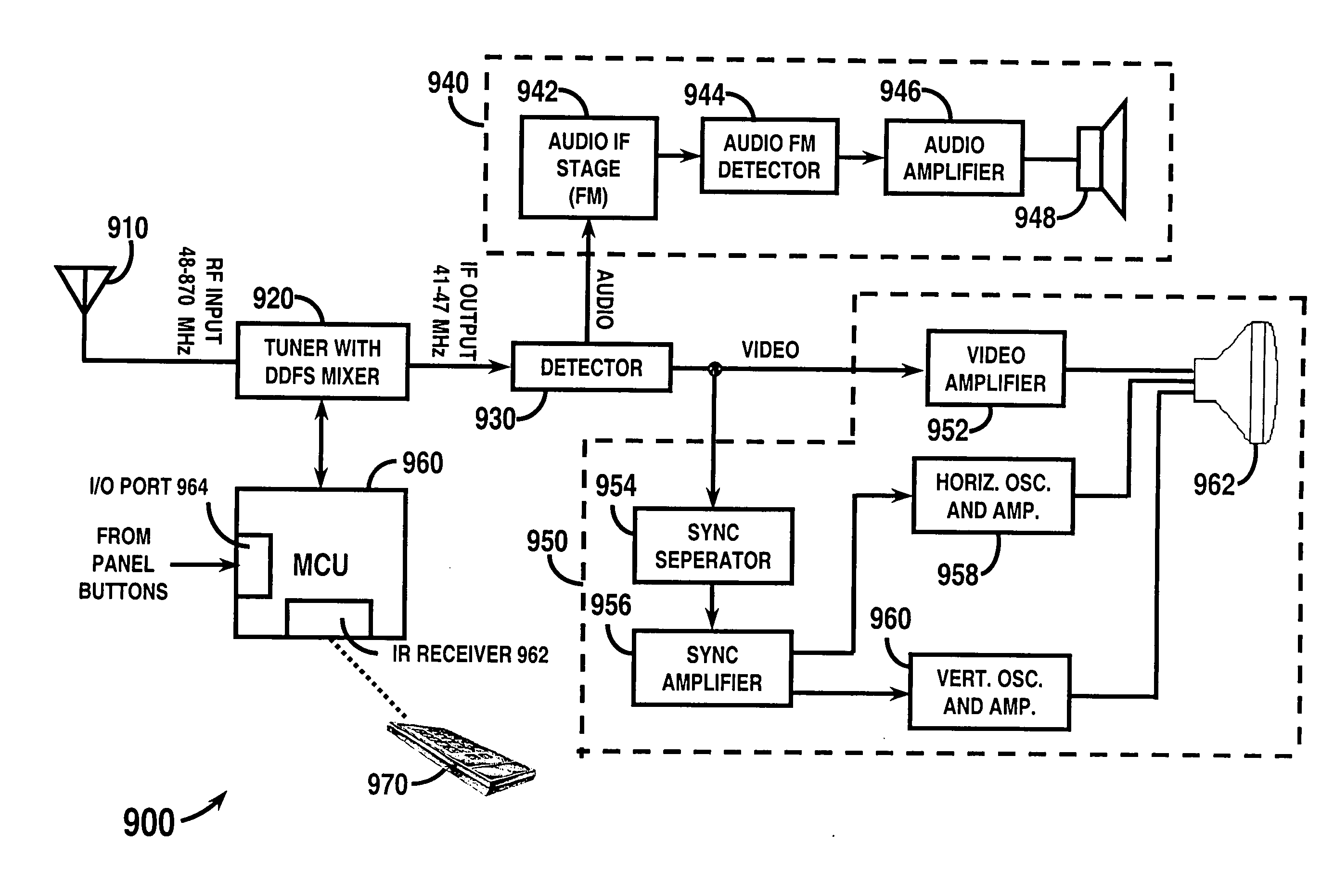
[0063] Television Implementation Example

[0064] The majority of television tuners used today are discrete single conversion tuners. Typical television tuners have inputs for receiving a radio frequency (RF) signals from an antenna or cable source having channels in the range of 48 megahertz (MHz) to 870 MHz. A tracking bandpass filter is often used to receive the RF INPUT signal and to attenuate undesired channel energy in order to provide a filtered signal to an input of a low noise amplifier (LNA). An RF synthesizer is often used to control a variable local oscillator (LO) provide a mixing signal in the range of 95 to 911 MHz. The mixing signal is combined with the output of the LNA in a mixer, which mixes the desired channel to an intermediate frequency (IF) of 44 MHz. The output of the mixer is then amplified in a programmable gain amplifier (PGA) and is filtered in an IF filter having a center frequency at the conventional IF of 44 MHz and having a passband of 6 MHz. Thus the IF...

embodiment 850

[0094]FIG. 8B is a block diagram for an embodiment 850 including an integrated circuit 802 that includes tuners for multiple radio bands, and each of these tuners utilize the tuner circuitry of the present invention. For example, integrated circuit 802 includes an AM tuner 852, FM tuner 854, and any other desired radio band as represented by tuner 856. As shown, the AM tuner 852 receives an RF input signal from antenna 858 and utilizes in part tuner 10A, according to the present invention, to generate tuned AM signals. The FM tuner 854 receives an RF input signal from antenna 862 and utilizes in part tuner 100B, according to the present invention, to generate tuned FM signals. And the other band tuner 856 receives an RF input signal from antenna 860 and utilizes in part tuner 100C, according to the present invention, to generate tuned signals in the other desired band. The different tuners 852, 854 and 856 can also use digital clock signals 808, 810 and 814 from a clock control circ...


PUM


Abstract

A television tuner (920) is adapted for use in a television receiver (900) that receives a radio frequency (RF) signal from an input device (910) and outputs audio and video information from a selected channel in response thereto. The television tuner (920) includes a direct digital frequency synthesizer (206) and a mixer (220). The direct digital frequency synthesizer (206) has an output for providing a digital representation of a mixing signal. The mixer (220) has a signal input for receiving a television signal, a mixing input coupled to the output of said direct digital frequency synthesizer (206), and an output for providing an intermediate frequency (IF) television signal.

Description

RELATED APPLICATIONS [0001] This application is a continuation-in-part of U.S. patent application Ser. No. 10 / 784,838 entitled “Tuner for Radio Frequency Receivers and Associated Method,” filed Feb. 23, 2004, which is a continuation-in-part of U.S. patent application Ser. No. 10 / 375,967 entitled “Local Oscillator and Mixer for Radio Frequency Receiver and Related Method,” filed Feb. 28, 2003 and U.S. patent application Ser. No. 10 / 377,573 entitled “Tuner Suitable for Integration and Method For Tuning a Radio Frequency Signal,” filed Feb. 28, 2003, all of which were invented by Richard A. Johnson and assigned to the assignee hereof, the entire text and all contents of which are hereby expressly incorporated by reference in their entirety.TECHNICAL FIELD [0002] The present invention relates generally to television receivers, and more particularly to improved television tuners and television receivers using such tuners. BACKGROUND [0003] Radio frequency (RF) receivers are used in a wid...

Claims


Application Information

Patent Timeline
IPC IPC(8): H03C3/40H03D7/14H03D7/16
CPCH03C3/403H03D7/1441H03D2200/009H03D7/1433H03D7/1458H03D7/166
Inventor JOHNSON, RICHARD A.
Owner XENOGENIC DEV LLC
Why Eureka
Try Eureka