Motor for washing machine

a technology for washing machines and motors, applied in the direction of magnetic circuit rotating parts, mechanical energy handling, shape/form/construction, etc., can solve the problems of rotors liable to deformation by external impact, plastic rotors of related art washing machines have hazards, etc., to improve the safety of washing machine operation, simple fabrication, and simplified injection molding

Inactive Publication Date: 2005-06-30
LG ELECTRONICS INC
View PDF9 Cites 49 Cited by
  • Summary
  • Abstract
  • Description
  • Claims
  • Application Information

AI Technical Summary

Benefits of technology

[0012] An object of the present invention is to provide a motor for a washing machine which can improve security of operation of the washing machine.
[0013] Another object of the present invention is to provide a motor for a washing machine which requires simplified injection molding to enable simple fabrication to save production costs.
[0018] Thus, the washing machine of the present invention can make stable operation even at spinning, and reduce hazard of current leakage.

Problems solved by technology

A rotor of a related art motor for the washing machine which is entirely injection molded of plastic, requires a complicated mold and fabrication process, and is liable to shrinkage during cooling of the injection molded plastic, thereby being unable to obtain an original shape.
The plastic rotor of the related art washing machine has a hazard in that the rotor is liable to deform by an external impact.
Also, the complicated rotor shape complicates the mold used for injection molding, thereby making injection molding difficult.
Moreover, since the injection molded plastic may undergo deformation after the injection molding, an injection molded body is liable to have a shape different from a desired shape.
If fabrication of the rotor frame 1 to exact dimensions fails due to deformation that occurs during the injection molding process, particularly, a cooling process, the rotor frame 1 causes interference with other parts, such as a stator of the motor, thereby potentially causing the inoperability of a washing machine which uses these parts.
If the plastic is flexible, the rotor frame 1 may be deformed by external force which may occur during operation of the washing machine, and interfere with other parts, thereby potentially causing the inoperability of a washing machine inoperative which uses these parts.

Method used


Image

  • Motor for washing machine
  • Motor for washing machine
  • Motor for washing machine

Examples


second embodiment

[0070]FIG. 9 illustrates a section of key parts of a motor in accordance with a second preferred embodiment of the present invention. The motor in accordance with a second preferred embodiment of the present invention illustrated in FIG. 9 is identical or similar to the motor in accordance with a first preferred embodiment of the present invention in most of the parts, except that the motor of the second embodiment has the bushing 170 fastened from an underside of the rotor frame 141 in an upward direction.

[0071] In other words, similar to the first embodiment, the shaft supporting housing 60 is secured to an inside of the bushing 170 as the shaft supporting housing 60 is insert molded with the bushing 170. Different from the first embodiment, the seating projections 171 are projected upward from the bushing 170, and the seating flange 151 is projected upward from the rotor frame 141. This structure enables the bushing 170 to be placed from a lower side to an upper side of the rotor...

fifth embodiment

[0079] In more detail, the bushing 470 of the fifth embodiment motor has three bushing side fastening holes 472 at regular intervals. There is the seating projection 471 on an underside of the bushing 470 in the vicinity of each of the bushing side fastening holes 472 for reinforcing the bushing side fastening hole 472.

[0080] At a center of the rotor frame 441, there is a seating flange 451 for placing the bushing 470, and three frame side fastening holes 450 aligned with the bushing side fastening holes 450 for fastening the bushing 470 to the rotor frame 441 after the bushing 470 is placed thereon. There is a seating guide 449 on an outer side of each of the frame side fastening holes 450. It is preferable that the seating guide 449 and the frame side fastening hole 450 are positioned in the same radial line, and a distance between each pair of the seating guide 449 and the frame side fastening hole 450 is the same.

[0081] It is preferable that the seating projection 471 has a rig...

seventh embodiment

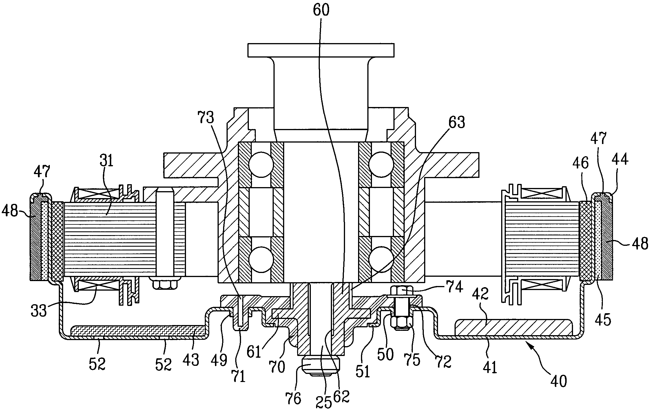
[0090] In the motor of the seventh embodiment, a shaft supporting housing 60 is insert molded with a rotor frame 641 after the shaft supporting housing 60 is placed at a proper position inside a housing inserting hole 642 at a center of the rotor frame 641, such that the shaft supporting housing 60 is secured at a position, and the injected resin forms a bushing 670.

[0091] That is, the bushing 670 is not fastened to the rotor frame 641, not with fastening members, like the bolts and nuts, but fixedly secured to the rotor frame 641 by insert molding with liquid resin injected toward a position in the vicinity of the housing insertion hole 642 after the bushing 670 is placed in the same mold with the rotor frame 641 and the shaft supporting housing 60.

[0092] The housing insertion hole 642 of the rotor frame 641 has a first bent surface 649 on an inside circumferential surface. The rotor frame 641 also has sustaining holes 647 at portions where the rotor frame 641 is connected with th...


PUM


Abstract

A motor for a washing machine including a driving shaft coupled to a drum, a stator for forming a magnetic field with a coil wound on a core, and a rotor rotatably mounted on an outside of the stator coupled to the driving shaft for driving the driving shaft, wherein the rotor includes a rotor frame having magnets attached to an inside surface of an outer end, a back yoke on an outside surface of the outer end for reinforcing the rotor frame and forming a magnetic path, a shaft supporting housing at a center of the rotor frame having one end portion of the driving shaft secured thereto, a bushing of a non-conductive resin having the shaft supporting housing formed as one body at a center, the bushing being secured to the rotor frame, and fastening members for fastening the bushing to the rotor frame.

Description

CROSS-REFERENCE TO RELATED APPLICATIONS [0001] This application claims the benefit of Korean Application Nos. P2003-0097838, P2003-0097839, P2003-0097840, P2003-0097841, all of which were filed on Dec. 26, 2003, and are hereby incorporated by reference as if fully set forth herein. BACKGROUND OF THE INVENTION [0002] 1. Field of the Invention [0003] The present invention relates to motors for washing machines, and more particularly, a direct coupling type motor for a washing machine, which is directly coupled to a drum of the washing machine, for rotating the drum. [0004] 2. Discussion of the Related Art [0005] A rotor of a related art motor for the washing machine which is entirely injection molded of plastic, requires a complicated mold and fabrication process, and is liable to shrinkage during cooling of the injection molded plastic, thereby being unable to obtain an original shape. [0006]FIG. 1 illustrates a section of a rotor of a motor of a related art washing machine. [0007] R...

Claims


Application Information

Patent Timeline
Patent Type & Authority Applications(United States)
IPC IPC(8): D06F37/40D06F37/20D06F37/30H02K1/27H02K1/30H02K5/15H02K7/14H02K21/22
CPCD06F37/304H02K1/2786H02K21/22H02K7/14H02K1/30H02K1/2791
Inventor LEE, DEUG HEECHOI, SEUNG BONGAHN, BYUNG HWAN
Owner LG ELECTRONICS INC
Why Eureka
Try Eureka