

Disc accessing apparatus and the panel thereof
- Summary
- Abstract
- Description
- Claims
- Application Information
AI Technical Summary
Benefits of technology
Problems solved by technology
Method used
Image

Examples
Embodiment Construction
[0016] The present invention provides a disc accessing apparatus and a panel thereof for guiding a disc out normally. In case the disc cracks into pieces during high-speed rotation, the panel also prevents the pieces of a cracked disc from jetting out of the disc accessing apparatus.
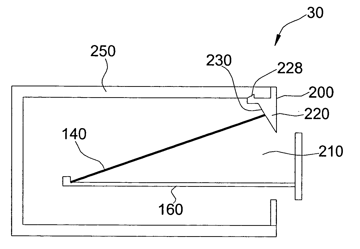
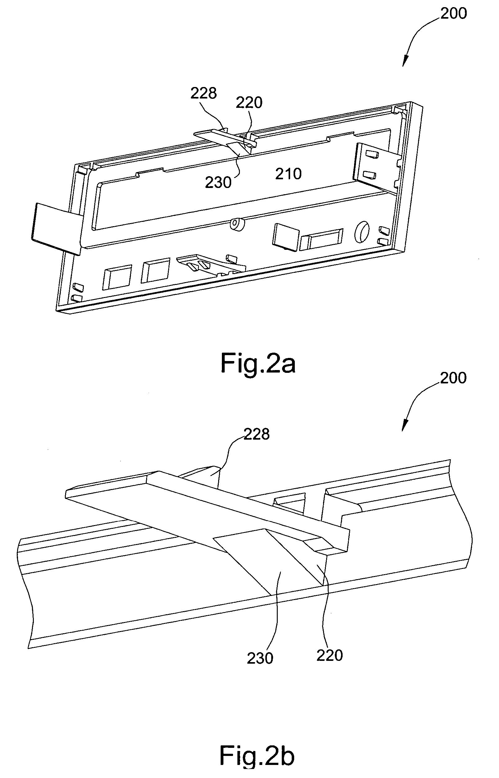
[0017] In accordance with a panel of an embodiment of the present invention, as shown in FIG. 2a and FIG. 2b, the panel 200 includes an opening 210, a wedge portion 220 and an engagement portion 228. The opening 210 allows a disc 140 (shown in FIG. 3) to pass. The engagement portion 228 here mentioned is a latch, which is used to engage the panel 200 with a housing 250 (shown in FIG. 3) of the disc accessing apparatus 30 (shown in FIG. 3). The wedge portion 220, placed near the opening 210, provides a surface 230 slanted towards the opening 210. In this embodiment, the wedge portion 220 and the panel 200 are formed integrally. For example, the panel 200 extends inwardly to form the surface 230.
[0018]FI...
PUM
 Abstract
Description
Claims
Application Information