AI technical title is built by Patsnap AI team. It summarizes the technical point description of the patent document.
a fixed bone and variable angle technology, applied in the field of locking bone fixation assembly, can solve the problems of cumbersome manipulation and cumbersome multi-component traditional plate assembly, and achieve the effect of simple effective and strong locking
Active Publication Date: 2005-07-28
SYNTHES USA
View PDF20 Cites 437 Cited by
Summary
Abstract
Description
Claims
Application Information
AI Technical Summary
This helps you quickly interpret patents by identifying the three key elements:
Problems solved by technology
Method used
Benefits of technology
Benefits of technology
[0010] Is therefore an object of the present invention to provide a simple effective and strong locking mechanism for locking the bone screw to the fixation device.
[0011] Another object of the present invention is to provide a new and novel method of fixation, having a polyaxial coupling of the screw to the fixation device, whereby a single fixation device is compatible with a wide range of screw-in angles.
[0012] Further, it is an object of the present invention to provide a method of bone fixation, which provides the surgeon with the greatest freedom to choose the most desirable angle to direct the bone screw while maintaining an effective locking mechanism.
[0013] The present invention by being an easy and straightforward procedure for the surgeon makes bone fixation simple and fast overcoming one of the most important subject of matter of actual surgery, time shortening.
[0014] By fulfilling the recently mentioned objects, the present invention is extremely helpful to the medical care area.
Problems solved by technology
These multi-component traditional plate assemblies can be cumbersome and tedious to manipulate during surgery to achieve the most desirable angle for directing the bone screw into the patient.
Method used
Image
Click on the blue label to locate the original text in one second.
Reading with bidirectional positioning of images and text.
Examples
Embodiment Construction
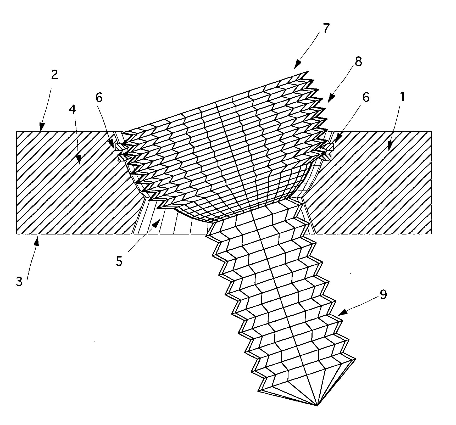
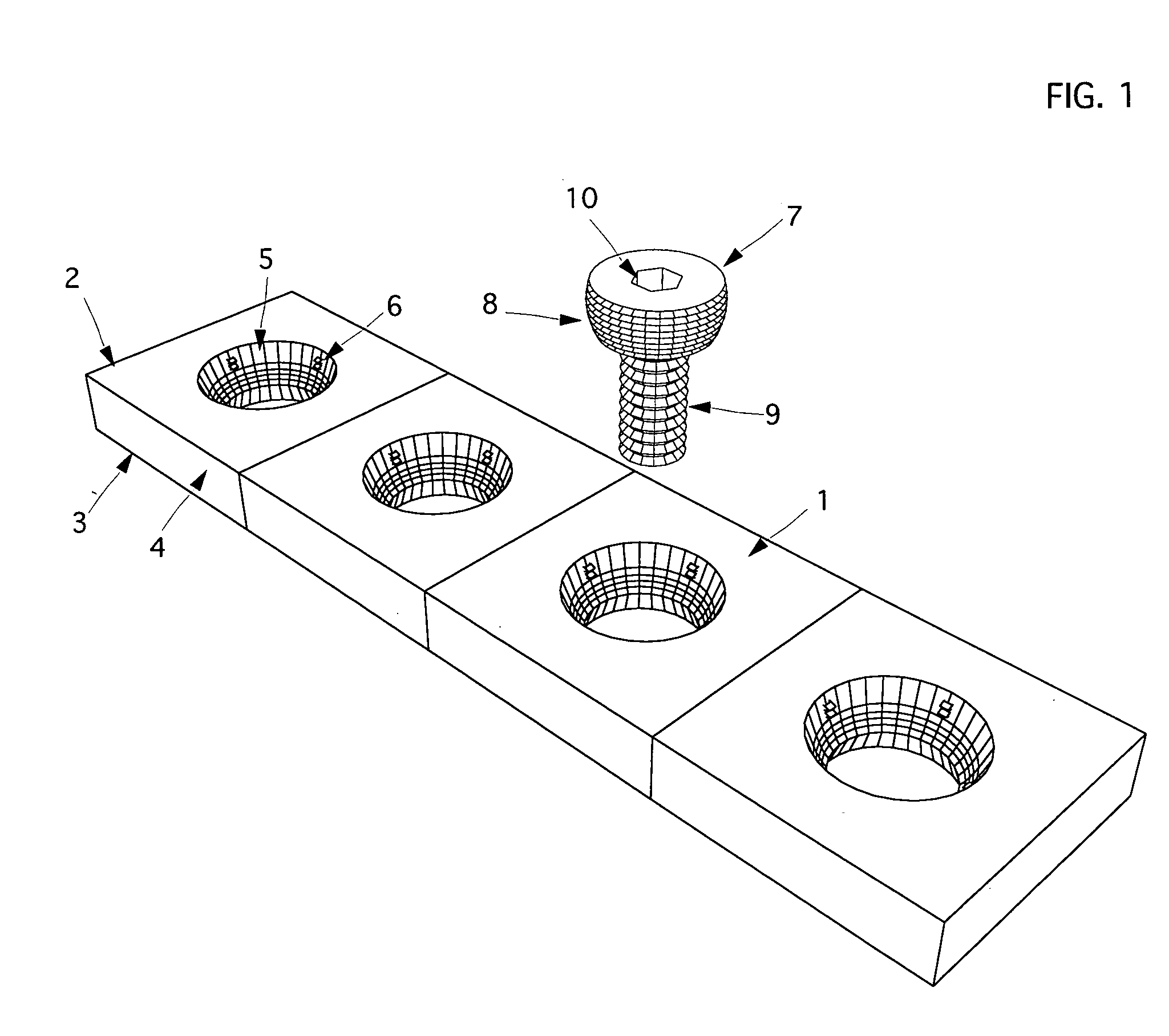
[0028] Hereinafter, a method of bone fixation according to the preferred embodiment of the present invention will be explained with reference to FIGS. 1-10.
[0029] The bone plate 1 shown in FIG. 1 comprises substantially an upper side 2 and a lower side 3 intended to be closer to the bone than the upper side 2, and a number of plate holes 5 that extend from upper 2 side to lower side 3.
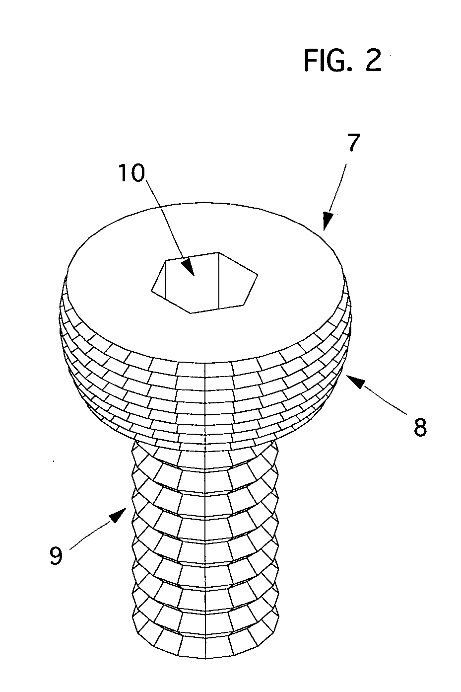
[0030] As best shown in FIG. 2, the screws 7 have a head 8 and a shank 9. The head 8 is shaped like a sphere and is threaded with a constant pitch substantially equal to the pitch of the threaded shank 9, and wherein an insertion / extraction hole 10 is cut for the connection of the insertion / extraction tool. The thread cut in the screw head 8 has a double entry, keeping substantially the same pitch of the thread of the shank 9. The thread profile may vary according to the requirements and according to the mechanical properties of the used alloy.
[0031]FIG. 3 shows a circle 11 as a projection of the sp...
PUM
Abstract
A bone fixation assembly for securing a fixation device such as a bone plate, to bone includes a fixation device, including at least a through hole with isolated protrusions (such as pegs or spikes); and locking bone engaging members such as screws. The screw has a shank with a thread for engaging bone and a partial sphere head with a thread configured and dimensioned to match with the isolated protrusions of the hourglass shaped through holes of the bone plate. The bone plate has a through hole shaped like an hourglass which diameter matches that of the screw spherical head and is provided with multiple isolated protrusions. In use, the screw is threaded into the bone, through the hole of the bone plate at a selected angle. The partial sphere head of the screw engages in the protrusions of the plate hole resulting in the strong locking of the screw at the selected orientation within the through hole in just one single surgical action.
Description
CROSS-REFERNCE TO RELATED APPLICATIONS [0001] U.S. Patent Document 4,484,570November, 1984Sutter, et al.5,053,036October, 1991Perren, et al.5,151,103September, 1992Tepic, et al.5,269,784December, 1993Mast, Jeffrey W.5,607,426March, 1997Ralph, et al.5,954,722September, 1999Bono6,423,064July, 2002Kluger6,454,769September, 2002Wagner, et al.6,454,770September, 2002Klaue, Kaj6,565,569May, 2003Assaker, et al.6,575,975June, 2003Brace, et al.6,623,486September, 2003Weaver, et al.STATEMENT REGARDING FEDERALLY SPONSORED RESEARCH OR DEVELOPMENT [0002] Not applicable. REFERENCE TO SEQUENCE LISTING, A TABLE, OR A COMPUTER PROGRAM LISTING COMPACT DISC APPENDIX [0003] Not applicable BACKGROUND OF THE INVENTION [0004] The present invention is directed to a locked bone fixation assembly, and in particular to an assembly that allows for a surgeon-selected angle of the bone screw relative to the fixation device. [0005] Orthopedic fixation devices, both internal and external, are frequently coupled t...
Claims
Application Information
Patent Timeline
Application Date:The date an application was filed.
Publication Date:The date a patent or application was officially published.
First Publication Date:The earliest publication date of a patent with the same application number.
Issue Date:Publication date of the patent grant document.
PCT Entry Date:The Entry date of PCT National Phase.
Estimated Expiry Date:The statutory expiry date of a patent right according to the Patent Law, and it is the longest term of protection that the patent right can achieve without the termination of the patent right due to other reasons(Term extension factor has been taken into account ).
Invalid Date:Actual expiry date is based on effective date or publication date of legal transaction data of invalid patent.
Patent Type & AuthorityApplications(United States)

