Secure biometric device

a biometric and secure technology, applied in the field of optical biometric capture devices, can solve problems such as unpractical solutions, and achieve the effect of greater freedom in positioning

Active Publication Date: 2010-05-27
IDEMIA IDENTITY & SECURITY FRANCE
View PDF3 Cites 57 Cited by
  • Summary
  • Abstract
  • Description
  • Claims
  • Application Information

AI Technical Summary

Benefits of technology

[0013]The use of the mirror gives greater freedom in positioning the control unit relative to the sensor. Advantageously, the device includes a reflecting member surrounding at least part of the control unit, the reflecting member preferably comprising a plurality of reflecting facets forming angles between one another so as to provide the sensor with different angles of view of the control unit.
[0014]The reflecting member enables the sensor to detect the optical characteristics of the control unit simultaneously with different viewing angles.

Problems solved by technology

Nevertheless, that solution is not practical, for example because it introduces constraints on the design of the device (overall size, position), of compatibility with light rays, and of passages for cables or electrical harnesses, that require discontinuities in the protection element and thus potentially provide access to the protected elements.

Method used


Image

  • Secure biometric device
  • Secure biometric device
  • Secure biometric device

Examples


first embodiment

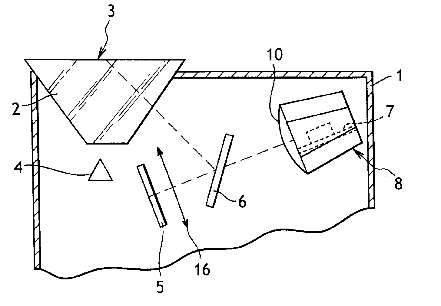
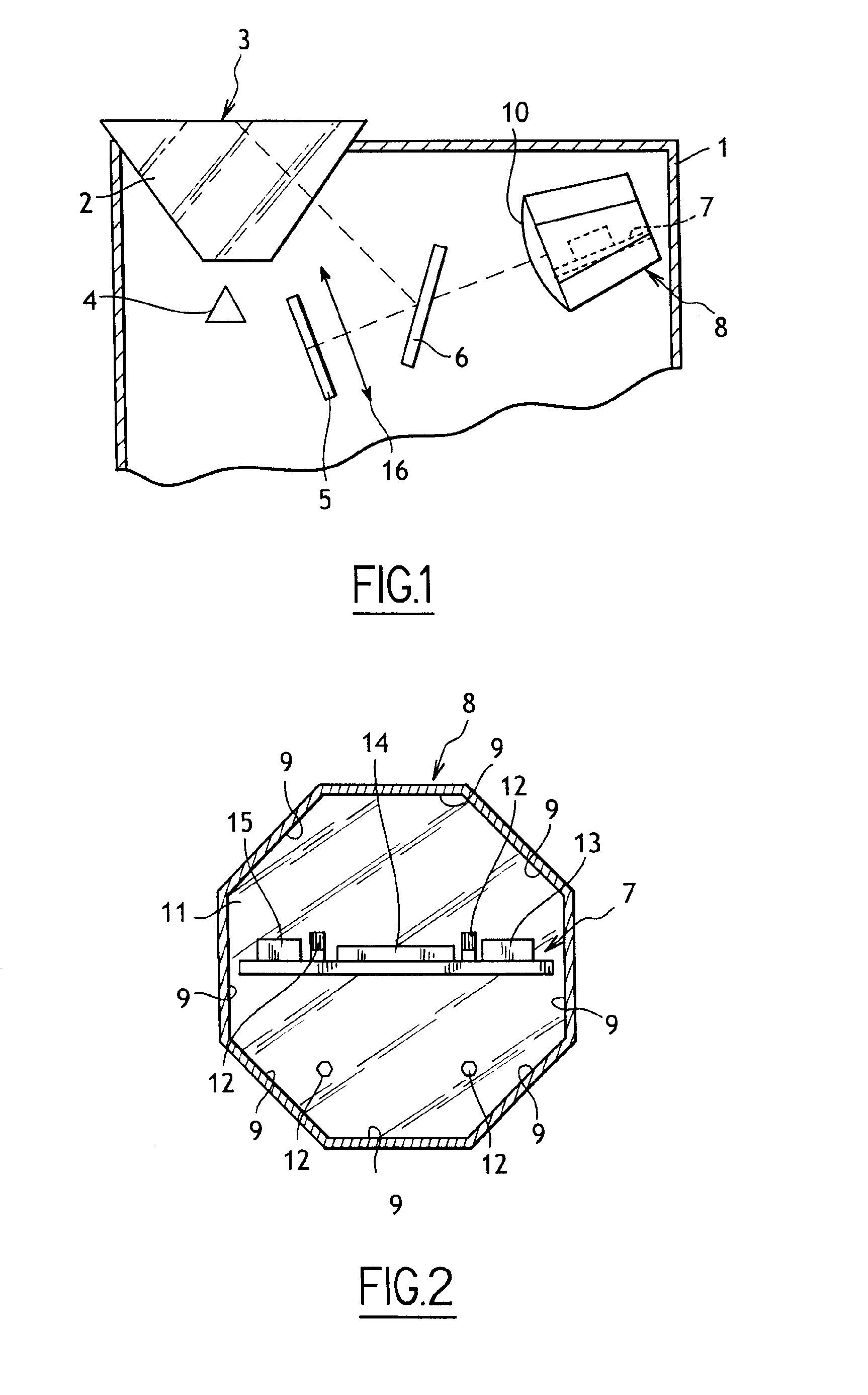
[0030]With reference to FIGS. 1 and 2, the capture device constituting the invention is shown arranged to perform identification by recognizing fingerprints.

[0031]The device comprises a casing 1 having a prism 2 mounted thereon in known manner, the prism having a top surface that serves as a surface against which a candidate for identification presses a finger. The top surface of the prism 2 is thus the fingerprint detection zone 3.

[0032]A light source 4 is located under the prism 2 for illuminating the detection zone 3.

[0033]The capture device includes a sensor 5, in this example forming part of a camera (not shown), that is located so that the sensor 5 has a field of view covering the detection zone 3.

[0034]A semi-reflecting mirror 6 is placed between the sensor 5 and the prism 2, in the field of view of the sensor 5, so as to define a light path between the sensor 5 and the detection zone 3 so that the detection zone 3 lies within the field of view of the sensor 5 after reflectio...

second embodiment

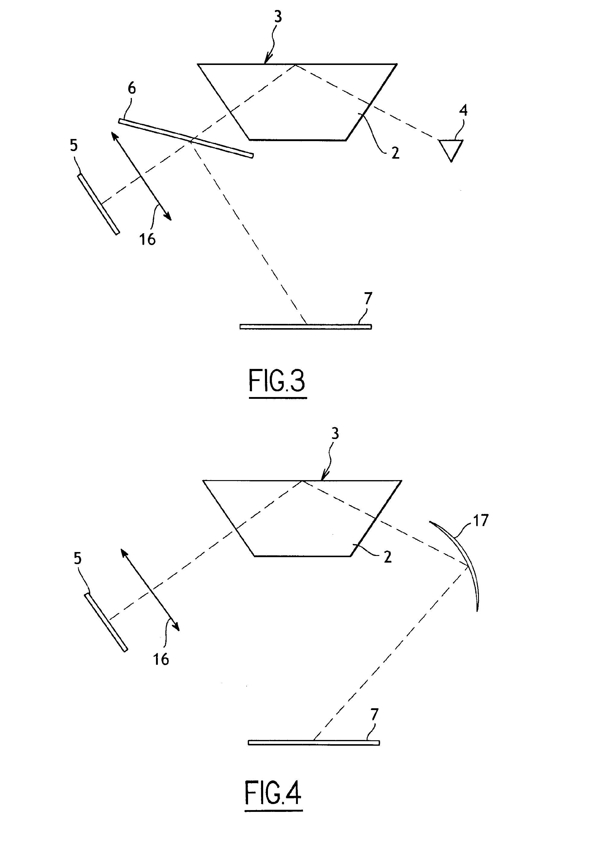
[0058]This embodiment variant is particularly simple. In a second embodiment variant shown in FIG. 4, the sensor 5 and the optical focusing element 16 are disposed in succession facing one of the side faces of the prism 2 so that the detection zone 3 is covered by the field of view of the sensor 5. A mirror 17 that presents optical power is placed facing the opposite side face of the prism 2 so as to reflect the top surface of the control unit 7 placed under the prism 2 onto the sensor 5 via the optical element 16 and the prism 2.

third embodiment

[0059]In a third embodiment variant, as shown in FIG. 5, the detection zone 3 of the prism 2 is surrounded by a reflecting surface 18 lying in the field of view of the sensor 5, which, together with an optical focusing element 16, is placed facing a side face of the prism 2. The control unit 7 and an optical focusing element 19 are disposed in succession facing the bottom face of the prism 2 so that portions of the control unit 7 are reflected in focus in the reflecting border 18.

[0060]Thus, the sensor 5 detects simultaneously (or in a variant sequentially) optical characteristics of the fingerprint appearing in the detection zone 3 and optical characteristics of portions of the control unit 7 reflected in the reflecting border 18.

[0061]In the description below of a second embodiment, elements that are identical or analogous to those described above are given the same references.

[0062]With reference to FIG. 6, the device constituting the second embodiment is arranged to provide iden...


PUM


Abstract

A device for capturing biometric characteristics, the device having an optical sensor with a field of view covering a detection zone for detecting optical characteristics, and an electronic control unit that is connected to the sensor in order to control it, the control unit being placed at least in part in the field of view of the sensor and includes a memory containing at least one signature resulting from at least one reference optical characteristic of the control unit as seen by the sensor, and a comparator module for comparing the signature with at least one corresponding signature that results from at least one optical characteristic of the control unit as supplied by the sensor.

Description

[0001]The present invention relates to a device for capturing an image of a fingerprint, of an iris of an eye, of a face, or of some other body part, e.g. for purposes of identifying or authenticating a person having the body part that appears in the image.BACKGROUND OF THE INVENTION[0002]In general, an optical biometric capture device comprises an optical sensor such as a camera and an electronic control unit connected to the sensor in order to control it. The control unit is arranged to control image capture by the sensor, image processing, and extracting characteristics concerning the captured body part for the purposes of:[0003]comparing them with characteristics stored in the device or imported via secure external communication; or[0004]exporting them to a comparator device via secure communication.[0005]The comparison serves to identify the person to whom said body part belongs or to verify that the characteristics of the body part appearing in the image do or do not belong to...

Claims


Application Information

Patent Timeline
Patent Type & Authority Applications(United States)
IPC IPC(8): G06F7/04G06V10/10
CPCG06F21/86G06K9/00046G06K9/78G06K9/00899G06K9/00885G06V40/1324G06V40/40G06V40/10G06V10/10
Inventor SALIBA, ERICDUFRESNE DE VIREL, FRANCOIS
Owner IDEMIA IDENTITY & SECURITY FRANCE
Why Eureka
Try Eureka