Method for steering smart antenna beams for a WLAN using MAC layer functions

a smart antenna and wlan technology, applied in the field of wireless local area networks, can solve the problems of distorted received signal itself, directional interference may be added, and it is difficult to accurately measure signal quality information

Inactive Publication Date: 2005-10-06
INTERDIGITAL TECH CORP
View PDF18 Cites 32 Cited by
  • Summary
  • Abstract
  • Description
  • Claims
  • Application Information

AI Technical Summary

Problems solved by technology

However, it is difficult to accurately measure signal quality information when the received signal includes undistorted signals plus random noise.
In addition, the received signal itself may be distorted and directional interference may be added in the received signal.
Consequently, signal quality information alone may not always be a reliable indicator of the quality of the radio link.
This is especially true in radio environments that are rich with interference coming from other client stations and access points, or other types of noise and interference sources.

Method used


Image

  • Method for steering smart antenna beams for a WLAN using MAC layer functions
  • Method for steering smart antenna beams for a WLAN using MAC layer functions
  • Method for steering smart antenna beams for a WLAN using MAC layer functions

Examples


Embodiment Construction

[0025] The present invention will now be described more fully hereinafter with reference to the accompanying drawings, in which preferred embodiments of the invention are shown. This invention may, however, be embodied in many different forms and should not be construed as limited to the embodiments set forth herein. Rather, these embodiments are provided so that this disclosure will be thorough and complete, and will fully convey the scope of the invention to those skilled in the art. Like numbers refer to like elements throughout, and prime notation is used to indicate similar elements in alternative embodiments.

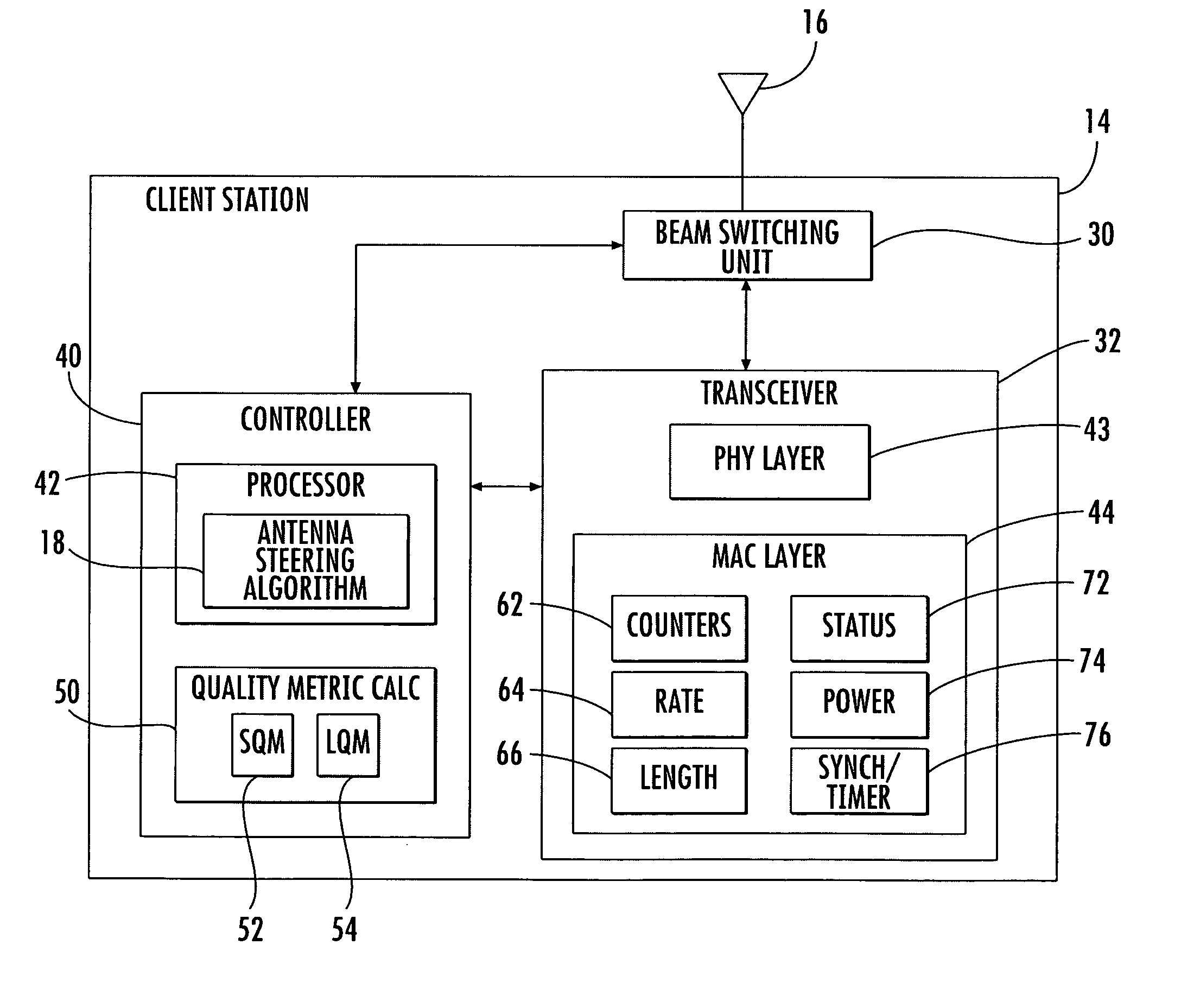
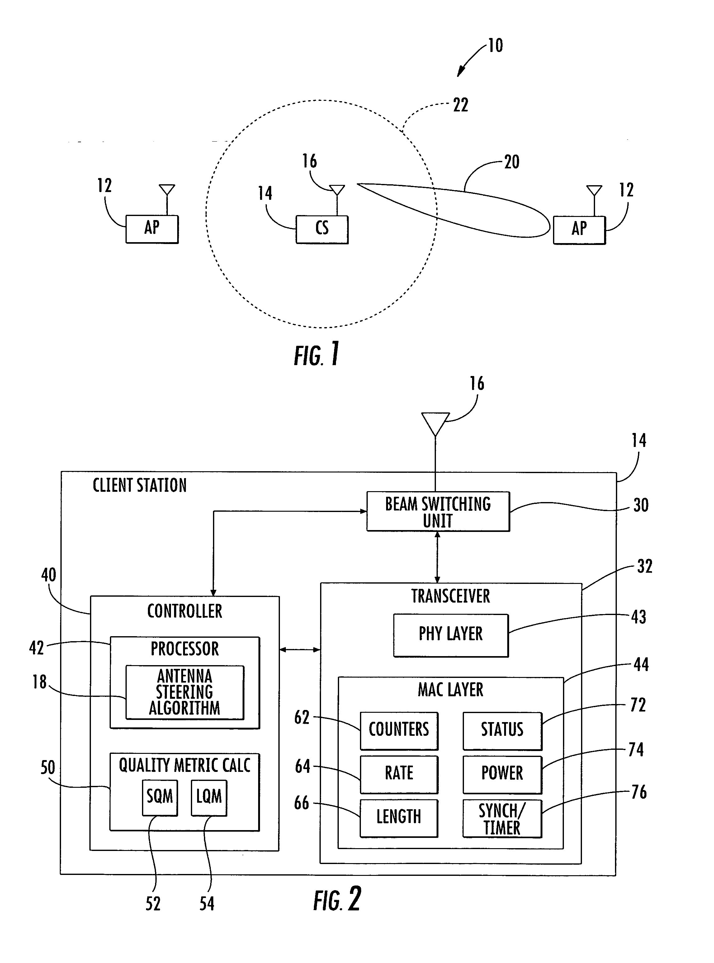
[0026] Referring initially to FIGS. 1 and 2, an 802.11 wireless local area network (WLAN) 10 includes an access point 12, and a client station 14 operating with a subscriber based smart antenna 16 in accordance with the present invention. The smart antenna 16, which will also be referred to as a switched beam antenna, generates a plurality of antenna beams in response to ...


PUM


Abstract

A smart antenna steering algorithm operates in response to different functions monitored by the media access control (MAC) layer within a client station. One function is when the MAC layer indicates that the client station has been placed in a power savings mode. In response, the antenna algorithm stores an index of the currently selected antenna. Another function is when the MAC layer indicates that the client station has not been synchronized, associated and authenticated with an access point. In response, the algorithm selects an omni-directional antenna beam as the default antenna beam. Another function is when the MAC layer provides beacon period synchronization information to the antenna steering algorithm so that the algorithm can update its own timer.

Description

RELATED APPLICATION [0001] This application claims the benefit of U.S. Provisional Application Ser. No. 60 / 553,902 filed Mar. 17, 2004, the entire contents of which are incorporated herein by reference.FIELD OF THE INVENTION [0002] The present invention relates to the field of wireless local area networks (WLANs), and more particularly, to an antenna steering algorithm for a smart antenna operating in a WLAN. BACKGROUND OF THE INVENTION [0003] Smart antenna technology is directed to antennas having the ability to change radio beam transmission and reception patterns to suit the environment within which radio communication systems operate. Smart antennas have the advantage of providing relatively high radio link gain without adding excessive cost or system complexity. [0004] Smart antenna technology has been used in wireless communication systems for decades, and has recently been investigated for use in wireless local area networks (WLANs). In a WLAN, a client station (CS) is a devi...

Claims


Application Information

Patent Timeline
Patent Type & Authority Applications(United States)
IPC IPC(8): H01Q3/00H04B1/06H04B7/04H04B7/06
CPCH04B7/0408H04B7/0617Y02D70/444Y02D70/20Y02D70/142H04B7/0695Y02D30/70H01Q3/005H01Q25/002
Inventor CHA, INHYOKZHAO, ZHENGGORSUCH, THOMAS ERICLINTELMAN, ROSS L.
Owner INTERDIGITAL TECH CORP
Why Eureka
Try Eureka