Optical recording medium, and recording method and recording apparatus for optical recording medium

a recording medium and recording method technology, applied in the field of optical recording mediums and recording methods and recording apparatuses for optical recording mediums, can solve the problems of affecting the accuracy of recording, so as to achieve accurate adjustment of recording power, good recording, and accurate adjustment

Active Publication Date: 2005-10-13
CMC MAGNETICS CORPORATION
View PDF15 Cites 51 Cited by
  • Summary
  • Abstract
  • Description
  • Claims
  • Application Information

AI Technical Summary

Benefits of technology

[0027] In the light of the above problems, an object of the present invention is to provide an optical recording medium having a plurality of recording layers on which information can be recorded by irradiating a laser beam from one side thereof, and a recording method and a recording apparatus for the optical recording medium which can determine an optimum recording power to each of the recording layers.
[0028] The recording method and the recording apparatus for the optical recording medium of this invention are aimed at accurately adjusting the recording power used when data is recorded on each of the layers even when the recording power is changed due to a change in temperature of the laser light source, for example, thereby accomplishing good recording on each of the recording layers.
[0061] Accordingly, it becomes possible to accurately adjust the recording power to be used when data is recorded on each of the recording layers, thereby to accomplish good recording on each of the layers.
[0062] An advantage of the recording method and recording apparatus for the optical recording medium according to this invention is that the recording power to be used at the time of recording of data on each of the recording layers can be accurately adjusted even when the recording power is changed due to, for example, a change in temperature of the laser light source, which allows good recording on each of the recording layer. As a result, when recording is continuously performed on a plurality of recording layers of an optical recording medium having the plural recording layers, for example, it is possible to perform good recording on each of the recording layers.

Problems solved by technology

However, when the laser diode continuously oscillates, the temperature is increased, thus the laser power tends to be decreased even at the same electric current value.
When the wavelength of the laser beam, which is the recording beam, shifts to the longer wavelength's side, the recording sensitivity deteriorates.
This causes a change in the laser power.
Even if the electric current value of the laser diode is so set and the laser power is so controlled as to provide the previously-determined optimum power, the laser power actually outputted may change due to a change in temperature of the laser diode, for example, which may make excellent recording difficult.
In the case where data is recorded in one recording layer and data is continuously recorded on the other recording layer, if the data is recorded on the latter recording layer with a laser electric current value corresponding to the optimum power beforehand determined, there is possibility that the data is not recorded or the recording is insufficient because the laser power is insufficient, which brings failure in excellent recording.
Particularly, when data is continuously recorded on plural recording layers, it is impossible to perform the OPC on each of the recording layers immediately before the recording is performed on each of the recording layer.
It is thus impossible to cope with changes in temperature of the laser light source, which obstacles attainment of excellent recording in each recording layer.

Method used


Image

  • Optical recording medium, and recording method and recording apparatus for optical recording medium
  • Optical recording medium, and recording method and recording apparatus for optical recording medium
  • Optical recording medium, and recording method and recording apparatus for optical recording medium

Examples


first embodiment

[A] First Embodiment

[0079] A recording method and a recording apparatus for an optical recording medium according to this embodiment can be applied to all optical recording media having a plurality of recording layers.

[0080] For example, it is preferable that the recording method and the recording apparatus of this embodiment are used to record data (information) in a single-sided incident type optical recording medium (single-sided incident type DVD), which has a plurality of recording layers, and in which data can be recorded on and read from the recording layers by irradiating a beam (laser beam) from one side thereof.

[0081] Particularly, the present invention is more effective when it is applied to an optical recording medium having dye containing recording layers because the recording sensitivity of the dye containing recording layer of, for example, a single-sided incident type DVD-R largely changes due to a change in wavelength of the laser beam.

[0082] As the single-sided ...

second embodiment

[B] Second Embodiment

[0319] According to this embodiment, the area structure of the optical recording medium and the optimization of the recording power differ from those of the first embodiment.

[0320] Hereinafter, description will be made of the area structure and the optimization of the recording power according to this embodiment.

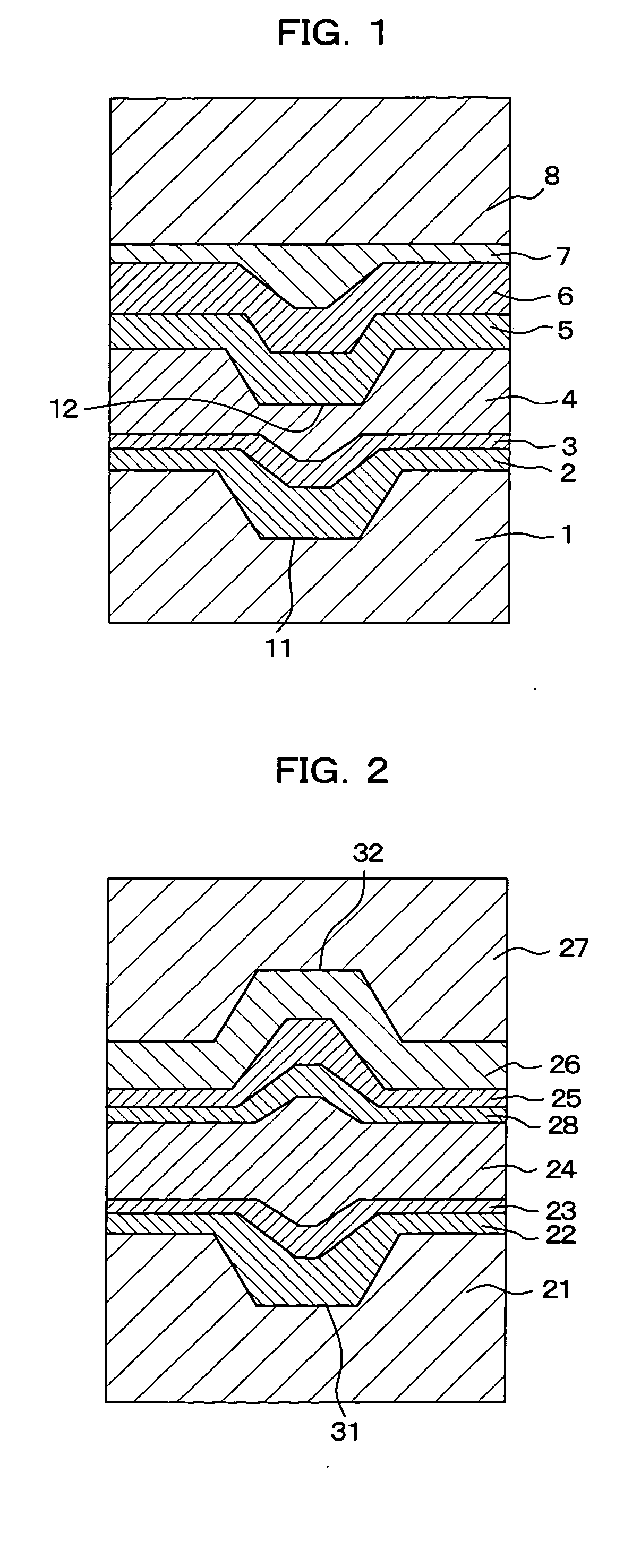
[0321] In this optical recording medium (of the type 1 and the type 2), recording is performed on the first recording layer 2 or 22 from the inner peripheral side toward the outer peripheral side, after that, the recording is performed on the second recording layer 5 or 25 from the outer peripheral side toward the inner peripheral side, as shown in FIG. 6(A).

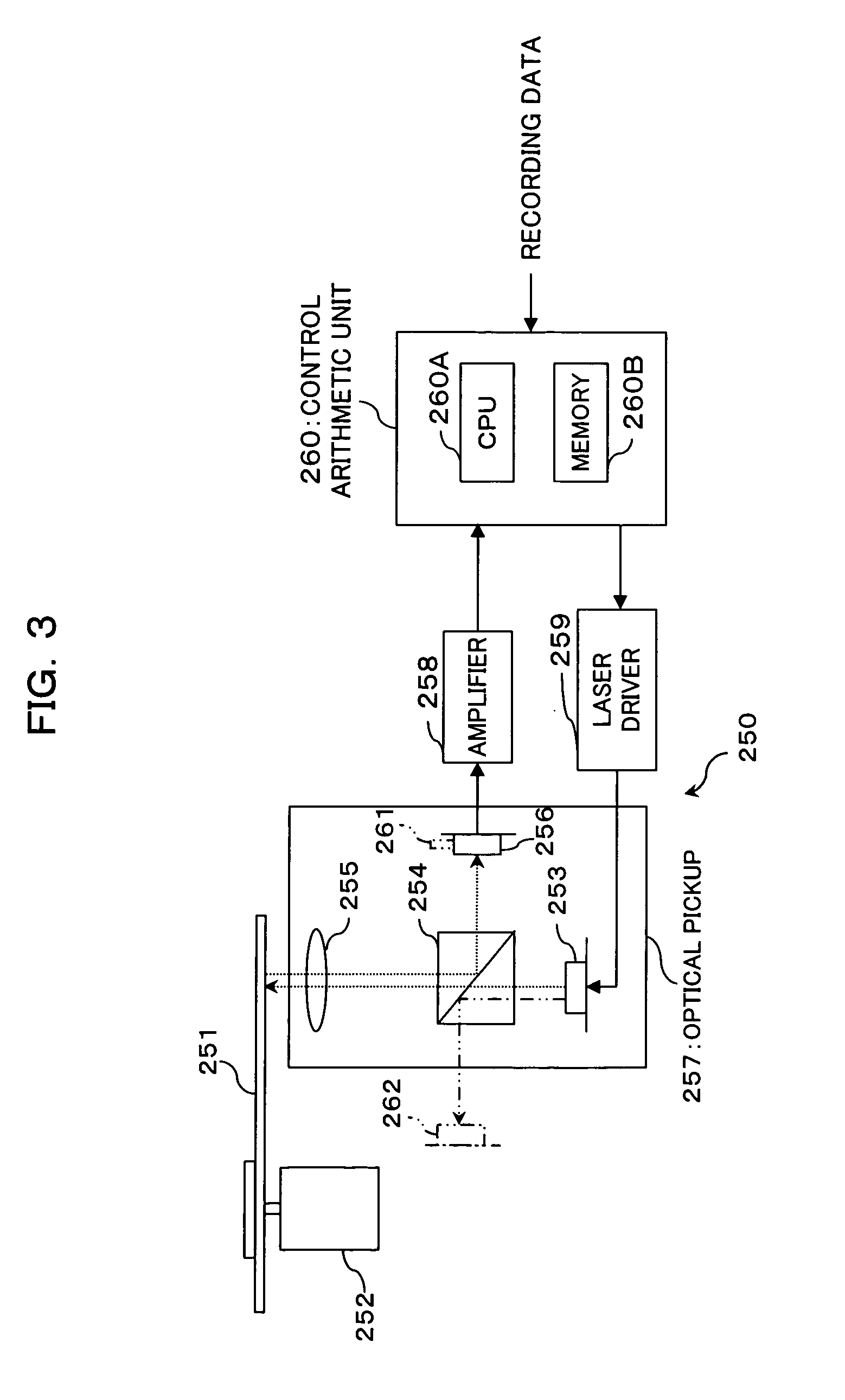
[0322] In this optical recording medium, optimization (OPC) of the recording power of the laser beam is performed for each of the recording layers using PCAs before actual recording is started on each of the recording layers, as well.

[0323] As shown in FIG. 6(A), a PCA 71, a user data area 73 and...

third embodiment

[C] Third Embodiment

[0341] According to this embodiment, the area structure of the optical recording medium and the recording power optimization differ from those according to the first embodiment.

[0342] Hereinafter, description will be made of the area structure of the optical recording medium and the recording power optimization according to this embodiment.

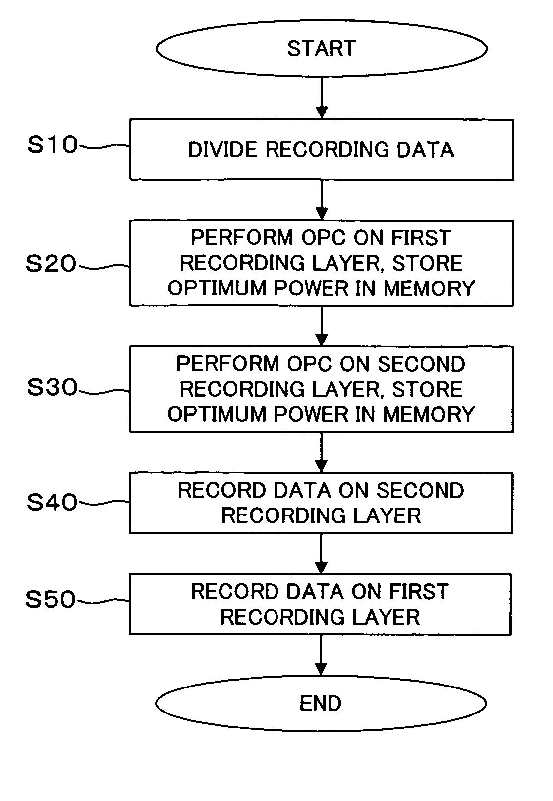
[0343] As shown in FIG. 7(A), in this optical recording medium (Type 1 and Type 2), recording is performed on the second recording layer 5 or 25 from the inner peripheral side toward the outer peripheral side, after that, recoding is performed on the first recording layer 2 or 22 from the outer peripheral side toward the inner peripheral side thereof.

[0344] In this optical recording medium, before recording is actually performed on each of the recording layers, optimization of the recording power of the laser beam (OPC) for each of the recording layer is performed, using PCAs.

[0345] As shown in FIG. 7(A), a PCA 101, a user ...


PUM

PropertyMeasurementUnit
transmittanceaaaaaaaaaa
thicknessaaaaaaaaaa

Abstract

In an optical recording medium having a plurality of recording layers on which information can be recorded by irradiating a laser beam from one side thereof, an optimum recording power to each of the recording layers can be determined. The optical recording medium has a plurality of recording layers on which information can be recorded by irradiating a laser beam from one side thereof, and each of the recording layers has a power calibration area (PCA) for optimizing the intensity of the laser beam.

Description

TECHNICAL FIELD [0001] The present invention relates to an optical recording medium having a plurality of recording layers, on which recording or reading are performed from one side thereof, and a recording method and a recording apparatus for the optical recording medium. BACKGROUND ART [0002] Various types of optical recording media such as CD-R, CD-RW, DVD-R, DVD-RW, DVD-ROM, MO and so forth are widely recognized and spread as external storages for information processing apparatuses such as computers because they can store a large volume of information and can be randomly accessed easily. With an increase in quantity of handled information, there is a demand to increase the recording density. [0003] Among various optical recording media, optical disks having a recording layer containing an organic dye (also referred to as a dye containing recording layer) such as CD-R, DVD-R, DVD+R and the like are particularly widely used because they are relatively inexpensive and have compatib...

Claims


Application Information

Patent Timeline
Patent Type & Authority Applications(United States)
IPC IPC(8): G11B7/00G11B7/007G11B7/125G11B7/1267
CPCG11B7/00736G11B2007/0013G11B7/24038G11B7/1267
Inventor KUBO, HIDEYUKITAKESHIMA, HIDEHARU
Owner CMC MAGNETICS CORPORATION
Why Eureka
Try Eureka