Ozone generating apparatus

a technology of generating apparatus and ozone, which is applied in the direction of ozone preparation, oxygen/ozone/oxide/hydroxide, electrical discharge ozone preparation, etc., can solve the problems of performance change, difficult to maintain ozone generation efficiency, and inability to achieve high ozone generation efficiency, etc., to achieve high degree of efficiency

Active Publication Date: 2005-10-13
MITSUBISHI ELECTRIC CORP
View PDF4 Cites 22 Cited by
  • Summary
  • Abstract
  • Description
  • Claims
  • Application Information

AI Technical Summary

Benefits of technology

[0012] It is an object of the present invention to provide an ozone generating apparatus capable of generating a high concentration of ozone ga

Problems solved by technology

It has, however, been confirmed that the use of the ultrapure oxygen as the source gas makes it impossible to generate a high concentration of ozone and makes it difficult to maintain the ozone generation efficiency, resulting in performance change with time, as disclosed in, for example, Japanese Patent Application Laid-Open No. 11-021110, paragraph 5.
The nitrogen that accompanies the source gas, however, inevitably gives rise to the production of NOX as a side effect in addition to a high concentration of ozone in a plasma field.
Experiments have shown that, for the discharge gap length of not greater than 1.0 mm or for generation of a high concentration of ozone, it is impossible to accomplish high ozone generation efficiency by employing a dielectric or a high-resistance film having a surface resistivity of not less than 1011 Ω as in a conventional technique or by simply increasing the number of locations in which

Method used


Image

  • Ozone generating apparatus
  • Ozone generating apparatus
  • Ozone generating apparatus

Examples


first preferred embodiment

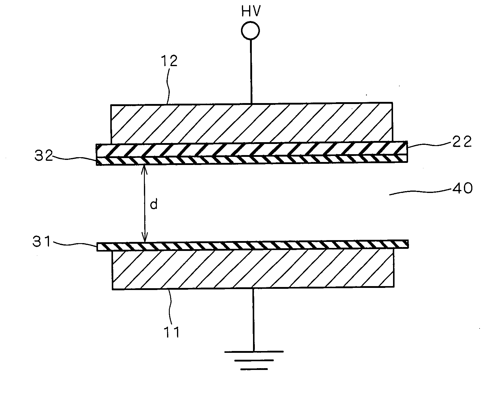
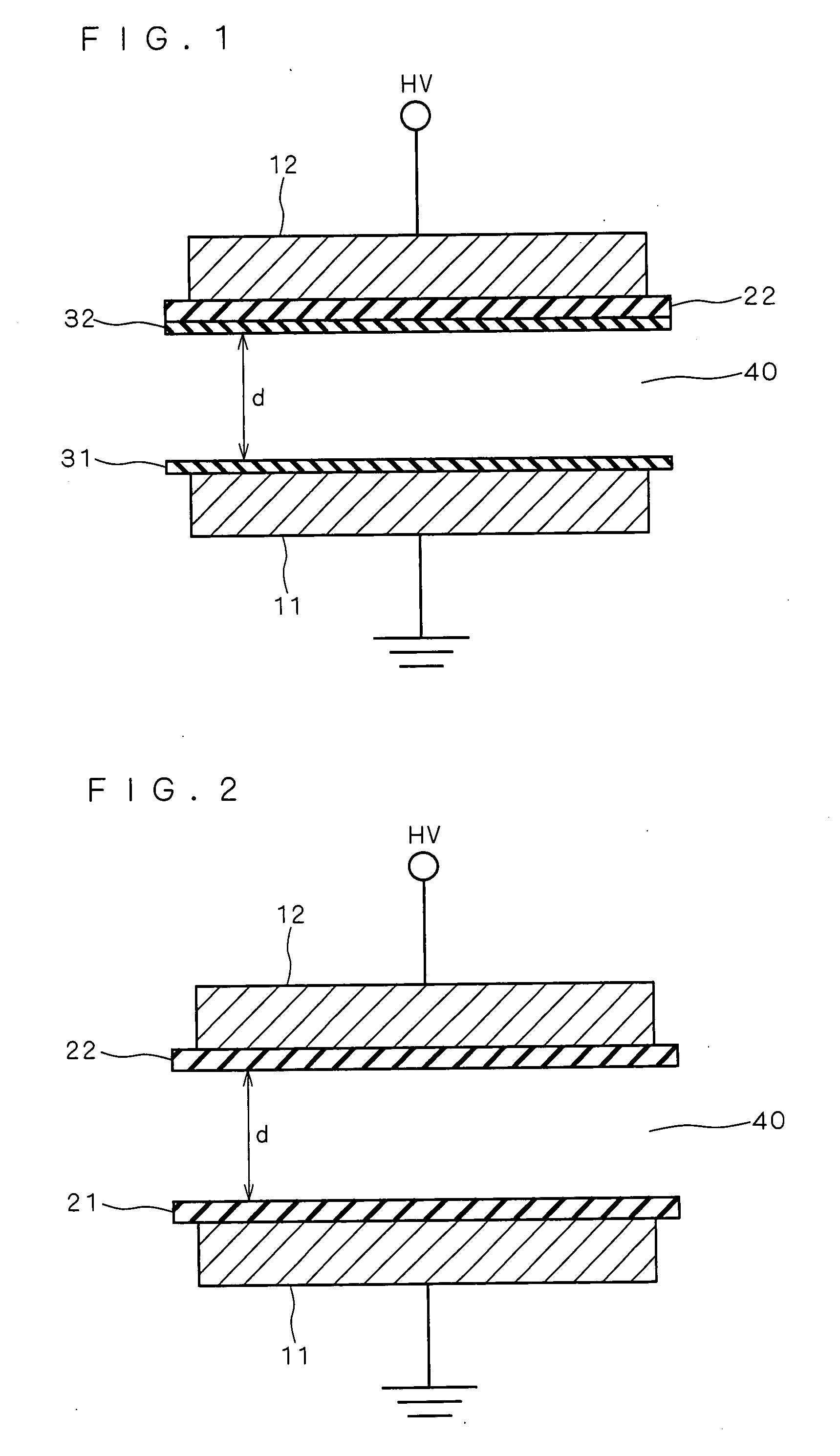
[0027]FIGS. 1 and 2 are views for illustrating an ozone generating apparatus according to a first preferred embodiment of the present invention. More specifically, FIG. 1 is a sectional view showing a construction of an electrode section according to the first preferred embodiment, and FIG. 2 is a sectional view showing a construction of a conventional typical parallel plate electrode section for use in a silent discharge ozone generating apparatus.

[0028] As illustrated in FIG. 2, the conventional typical parallel plate electrode section for use in the silent discharge ozone generating apparatus includes a pair of electrodes, i.e. an earthed electrode (metal electrode) 11 and a high-voltage electrode (metal electrode) 12, and dielectrics 21 and 22. The pair of earthed and high-voltage electrodes 11 and 12 are provided so that the dielectrics 21 and 22 lie between the pair of electrodes 11 and 12 and in contact with the pair of electrodes 11 and 12, respectively, and so that a certa...

second preferred embodiment

[0061]FIG. 5 is a view for illustrating the ozone generating apparatus according to a second preferred embodiment of the present invention and, more specifically, is a sectional view showing the construction of the electrode section according to the second preferred embodiment.

[0062] Effects similar to those of the first preferred embodiment are produced in the ozone generating apparatus including the electrode section with the construction as shown in FIG. 5 and having a discharge gap length d of 0.1 mm.

[0063] The construction of the electrode section shown in FIG. 5 differs from that of the first preferred embodiment in that the dielectric 21 is provided between the earthed electrode 11 and the low-resistance element 31 in the structure of the first preferred embodiment shown in FIG. 1. The remaining construction of the second preferred embodiment is identical with that of the first preferred embodiment. Alumina (having a volume resistivity of not less than 109 Ω·cm, a dielectri...

third preferred embodiment

[0067]FIG. 6 is a view for illustrating the ozone generating apparatus according to a third preferred embodiment of the present invention and, more specifically, is a sectional view showing the construction of the electrode section according to the third preferred embodiment.

[0068] Effects similar to those of the first preferred embodiment are produced in the ozone generating apparatus including the electrode section with the construction as shown in FIG. 6 and having a discharge gap length d of 0.1 mm.

[0069] The construction of the electrode section shown in FIG. 6 differs from that of the first preferred embodiment in that the earthed electrode 11 is not provided with the low-resistance element 31, but is in direct contact with the discharge in the structure of the first preferred embodiment shown in FIG. 1. The remaining construction of the third preferred embodiment is identical with that of the first preferred embodiment. Alumina (having a volume resistivity of not less than ...


PUM


Abstract

An ozone generating apparatus is provided which includes a pair of electrodes for producing a discharge by the application of an ac voltage therebetween, and at least one dielectric provided between the pair of electrodes. A source gas containing oxygen is provided into a discharge space in which the discharge is produced to generate ozone by the action of the discharge. A surface lying between at least one of the pair of electrodes and the discharge space and in contact with the discharge has a surface resistivity of 104 Ω to 1011 Ω. The source gas provided into the discharge space includes ultrapure oxygen having a purity of not less than 99.9%.

Description

BACKGROUND OF THE INVENTION [0001] 1. Field of the Invention [0002] The present invention relates to an ozone generating apparatus for generating a high concentration of clean ozone gas free of nitrogen oxides (NOX) by using ultrapure oxygen as a source gas. [0003] 2. Description of the Background Art [0004] In a conventional silent discharge ozone generating apparatus operating with a discharge gap length of about 1.0 mm or greater, a discharge occurring in a discharge space is made up of a multiplicity of micro-discharge streamers, as disclosed in, for example, Japanese Patent No. 3416982 (paragraphs 19 and 20), and Japanese Patent Application Laid-Open No. 7-277707 (1995) (paragraphs 19 and 20). In such a case, the increase in the number of locations in which the micro-discharge streamers occur promotes collisions between electrons and oxygen molecules to improve ozone generation efficiency. To increase the number of locations in which the micro-discharge streamers occur, Japanes...

Claims


Application Information

Patent Timeline
IPC IPC(8): B01J19/08C01B13/11H01T23/00
CPCC01B13/11C01B2201/12C01B2201/64C01B2201/34C01B2201/22C01B13/10
Inventor WADA, NOBORUKUZUMOTO, MASAKIINANAGA, YASUTAKA
Owner MITSUBISHI ELECTRIC CORP
Why Eureka
Try Eureka