Electro-mechanical cylinder lock-key combination with optical code

a technology of optical code and cylinder lock, which is applied in the direction of opto-electronic device actuation, cylinder lock, keyhole guard, etc., can solve the problems of environmental hazards, battery occupying valuable space, and often cumbersome battery replacement operation, and achieves a high degree of security

Inactive Publication Date: 2005-10-27
RUKO
View PDF18 Cites 40 Cited by
  • Summary
  • Abstract
  • Description
  • Claims
  • Application Information

AI Technical Summary

Benefits of technology

[0007] An object of the present invention is to provide a key and lock device of the kind initially mentioned, wherein a high degree of security is obtained while the space requirements are kept to a minimum.

Problems solved by technology

This poses a problem, particularly when fitting a new electro-mechanical lock in an existing installation.
However, the replacement of the battery is often a cumbersome operation.
Furthermore, the battery takes up valuable space, irrespectively of whether it is provided in the lock or in the key.
Also, batteries constitute an environmental hazard.
Another problem with today's electro-mechanical lock devices is that they must include not only mechanical locking elements but also the electronic circuitry and elements controlled by the electronic circuitry.
Yet another problem with prior art electro-mechanical lock devices is that when the key having correct mechanical code is inserted then all key-actuated moveable blocking elements are moved to non-blocking position; only the electro-mechanical blocking element remains to prevent the rotation of the cylinder core.

Method used


Image

  • Electro-mechanical cylinder lock-key combination with optical code
  • Electro-mechanical cylinder lock-key combination with optical code
  • Electro-mechanical cylinder lock-key combination with optical code

Examples


Embodiment Construction

[0028] In the following a detailed description of preferred embodiments of the present invention will be given.

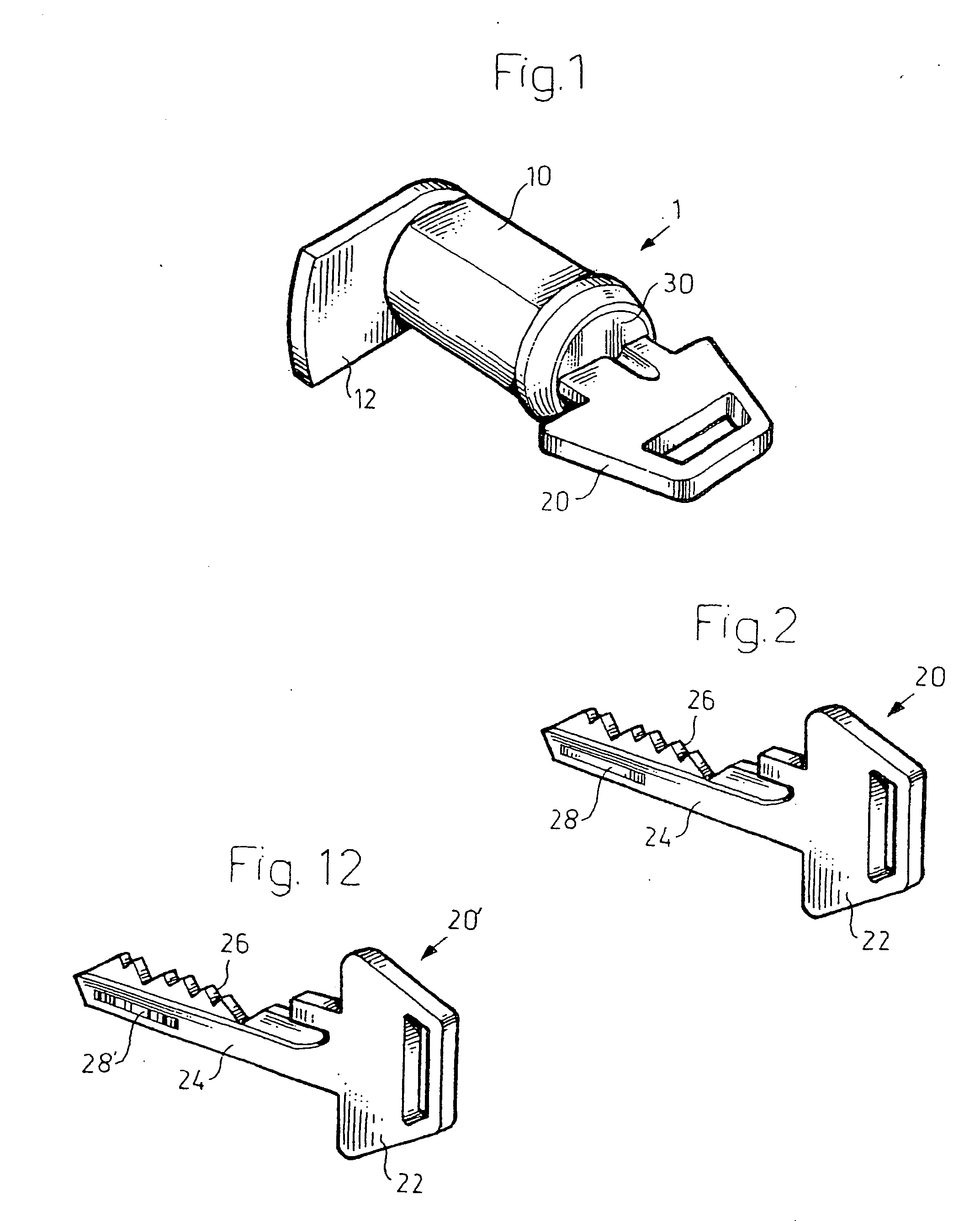
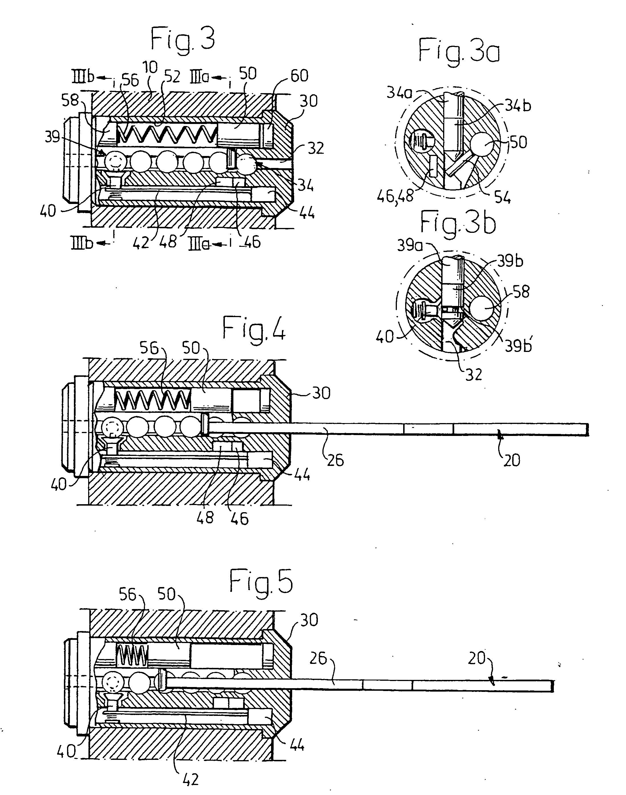
[0029] In FIG. 1, an overall perspective view of an electro mechanical cylinder lock-key combination 1 according to the invention is shown. The combination comprises a generally cylindrical cylinder housing 10 and a key 20 inserted into a key-way of a cylinder core 30 rotatably provided in the cylinder housing. By means of rotation of the key, a campiece 12 is actuated so as to act on a follower of a lock device. The cylinder housing 10 has the same general shape as conventional cylinder housings and the lock cylinder according to the invention can thus replace already installed all-mechanical lock cylinders.

[0030] The key 20 is shown in its entirety in FIG. 2. It has a conventional shape and comprises a grip portion 22 and a bit portion 24. The bit portion has an upper code surface 26 arranged to cooperate with tumbler pins provided in the lock cylinder.
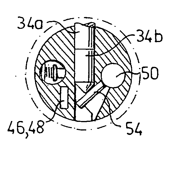
[0031] On a side...


PUM


Abstract

An electromechanical cylinder lock-key combination includes a cylinder housing and a cylinder core rotatably arranged in the cylinder housing and having a key-way for receiving a key. A plurality of key actuated moveable blocking elements block the rotation of the cylinder core unless a correct key is inserted in the key-way. An optical code reader in the lock reads an optical code element provided on an inserted key. At least one of said blocking elements functions as a bar element barring insertion of the key into the key-way unless a correct optical code element is provided on the key. By using at least one of the mechanical elements already present in the lock as part of the electronically controlled blocking mechanism, in combination with the use of an optical code requiring no moveable parts for the reading thereof, space requirements in the lock device are kept to a minimum.

Description

FIELD OF INVENTION [0001] The present invention relates generally to electro-mechanical key and lock devices and more particularly to an electro-mechanical cylinder lock-key combination using an optical code, such as a holographic code or a bar code provided on the key. BACKGROUND [0002] It is previously known a variety of lock devices that make use of electronically controlled elements for increasing the security of the lock. However, the demand for lock systems with a high level of security is constantly increasing. [0003] Many prior art electro-mechanical lock devices rely on a power source external to the lock device for powering the electronic circuitry of the device. This poses a problem, particularly when fitting a new electro-mechanical lock in an existing installation. [0004] One way to avoid this problem is to provide a replaceable battery either in the lock device or in the keys used with the lock device. However, the replacement of the battery is often a cumbersome opera...

Claims


Application Information

Patent Timeline
Patent Type & Authority Applications(United States)
IPC IPC(8): E05B47/06E05B49/00
CPCE05B47/0011E05B49/006E05B47/0626Y10T70/7079Y10T70/7102Y10T70/7605Y10T70/7616Y10T70/7768Y10T70/7977
Inventor LINDSTROM, ERIK
Owner RUKO
Why Eureka
Try Eureka