Optical transmitter and its control method

Inactive Publication Date: 2005-11-10
FUJITSU LTD
View PDF1 Cites 8 Cited by
  • Summary
  • Abstract
  • Description
  • Claims
  • Application Information

AI Technical Summary

Benefits of technology

[0024] Consequently, even when the amplitude of the input signal to the optical modulator is decreased due to a certain factor, the optical transmitter of the present in

Problems solved by technology

However, if the direct modulation method is used, there is the tendency that the influences of dynamic wavelength variations (chirping) in the optical output signal of the optical transmitter become increasingly large due to the influences of the wavelength dispersion in th

Method used


Image

  • Optical transmitter and its control method
  • Optical transmitter and its control method
  • Optical transmitter and its control method

Examples


Embodiment Construction

[0041] A description will now be given of preferred embodiments of the present invention with reference to the accompanying drawings.

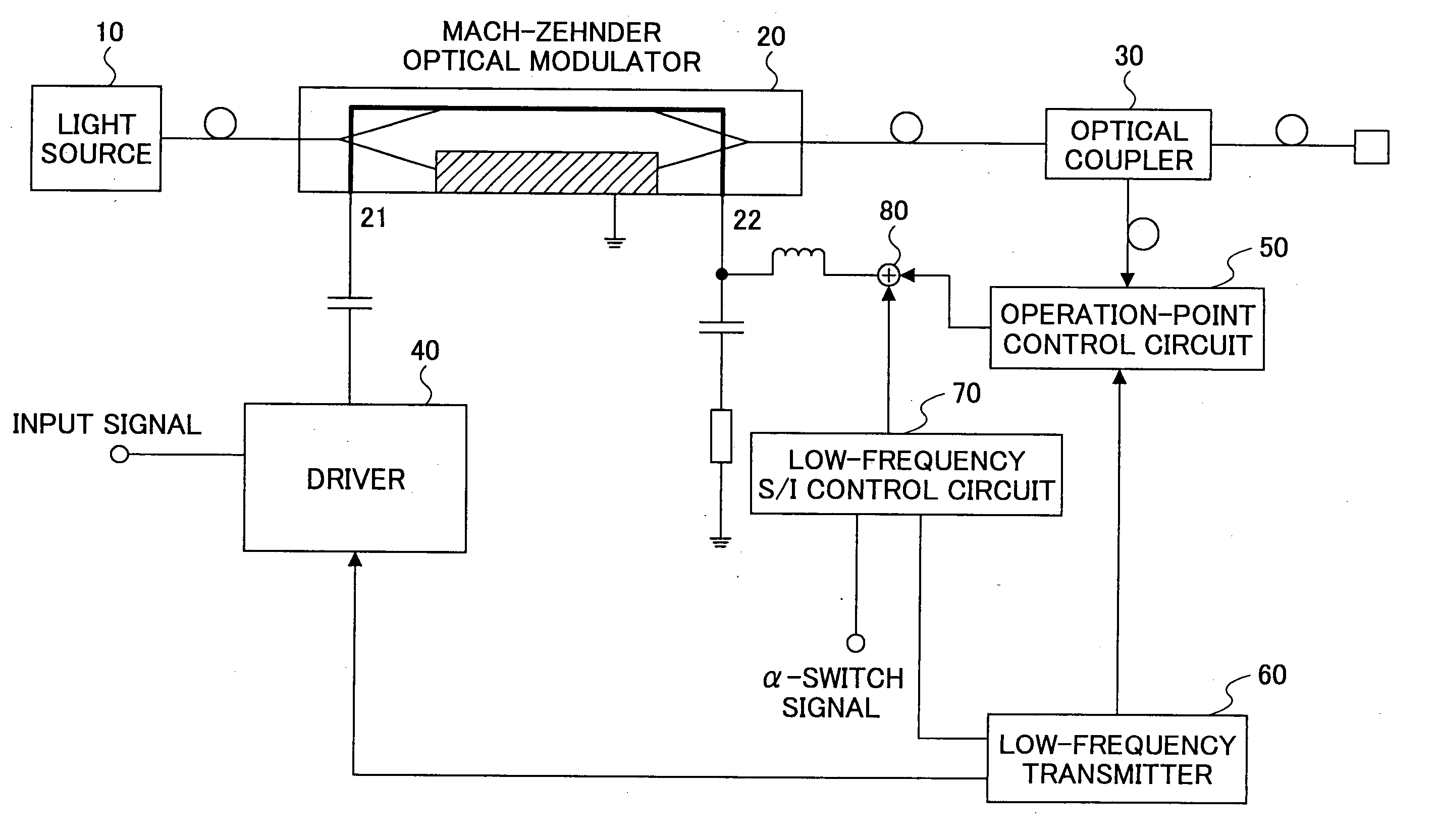
[0042]FIG. 4 shows the composition of an optical transmitter in the first preferred embodiment of the present invention.

[0043] As shown in FIG. 4, the optical transmitter of the present embodiment includes a light source 10 which emits a laser beam, a Mach-Zehnder optical modulator 20, and a driver circuit 40 which supplies a driving signal according to the input signal to one terminal 21 of the electrodes of the Mach-Zehnder optical modulator 20. The input signal is supplied to the optical modulator 20 via the driver circuit 40 from an external device (not shown).

[0044] The Mach-Zehnder optical modulator 20 modulates the laser beam emitted by the light source 10, in response to the input signal (the transmission signal) received via the driver circuit 40, in accordance with a predetermined modulation-characteristic curve of the optical modulator as...


PUM


Abstract

An optical transmitter comprises an amplitude modulation unit performing amplitude modulation of only a one-side amplitude of a main signal with a low-frequency signal having a predetermined frequency. An optical modulator receives an input signal generated after the one-side amplitude modulation, and modulates an incoming light in response to the received signal in accordance with a predetermined modulation-characteristic curve to output an optical output signal. An operating point control unit applies a predetermined bias voltage to the optical modulator to control a level of the input signal substantially applied to the modulation-characteristic curve so that the one-side amplitude of the main signal is applied to a minimum portion of the modulation-characteristic curve of the optical modulator.

Description

CROSS-REFERENCE TO RELATED APPLICATIONS [0001] This application is based upon and claims the benefit of priority from the prior Japanese patent application No. 2002-221720, filed on Jul. 30, 2002, the entire contents of which are incorporated herein by reference. BACKGROUND OF THE INVENTION [0002] 1. Field of the Invention [0003] The present invention relates to an optical transmitter provided with an optical modulator of, for example, Mach-Zehnder type, and a control method of the optical transmitter. More specifically, the present invention relates to an optical transmitter which is capable of effectively maintaining an extinction ratio of an optical modulator and improves the extinction ratio under given conditions, and a control method of the optical transmitter. [0004] 2. Description of the Related Art [0005] As for an optical transmitter used for an optical communication system, a direct modulation method that modulates a drive current to be supplied to a semiconductor laser i...

Claims


Application Information

Patent Timeline
IPC IPC(8): G02F1/03G02F1/01
CPCG02F1/0123H04B10/505H04B10/58H04B10/50575H04B10/50572G02F1/225
Inventor IMAI, KEISUKEYAMAZAKI, TORUINOUE, KAKUJIMISAIZU, SETSUONAGAKUBO, YASUNORI
Owner FUJITSU LTD
Why Eureka
Try Eureka