Dilation introducer for orthopedic surgery

a bone fixation device and introducer technology, applied in the field of bone fixation devices, can solve the problems of substantial trauma to the surrounding tissue, and achieve the effect of reducing the chance of damage to the surrounding soft tissue and minimal surgical procedures

a bone fixation device and introducer technology, applied in the field of bone fixation devices, can solve the problems of substantial trauma to the surrounding tissue, and achieve the effect of reducing the chance of damage to the surrounding soft tissue and minimal surgical procedures

US20050256525A1Inactive Publication Date: 2005-11-17INTERVENTIONAL SPINE

Image

  • Dilation introducer for orthopedic surgery
  • Dilation introducer for orthopedic surgery
  • Dilation introducer for orthopedic surgery

Examples


Embodiment Construction

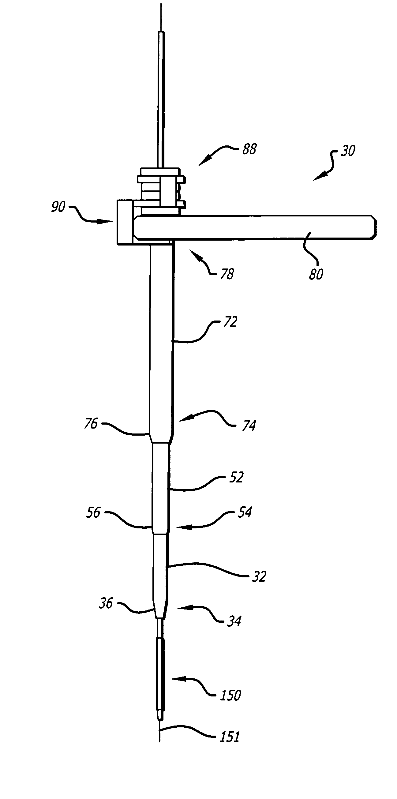
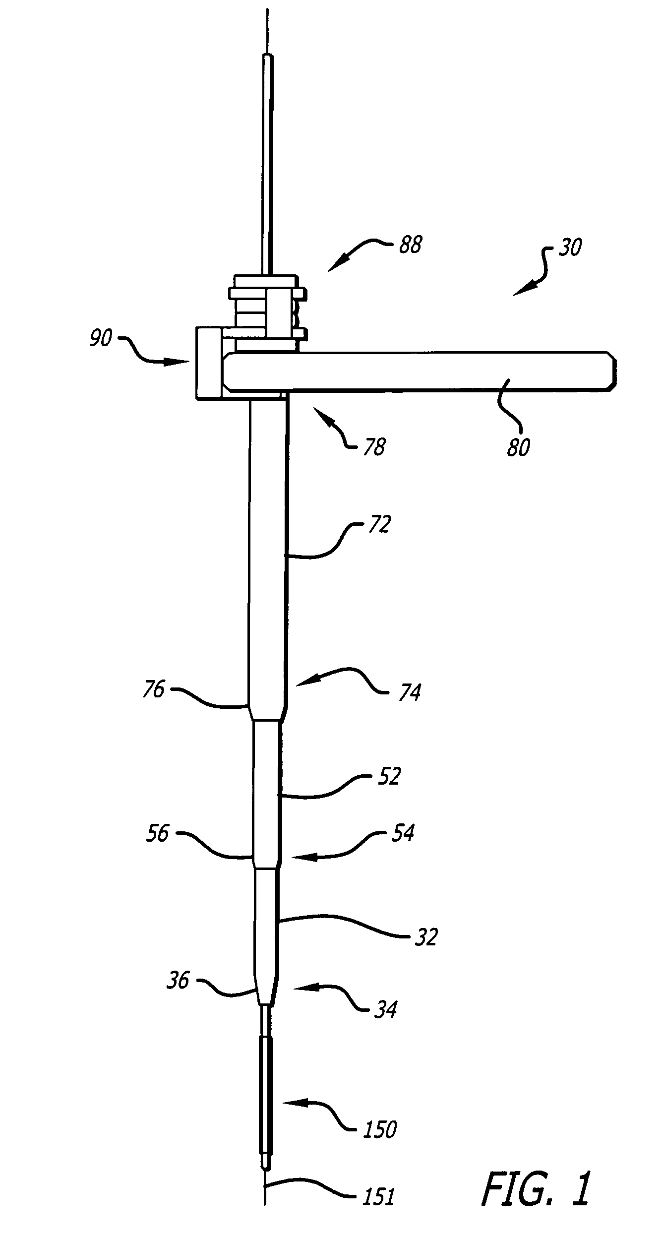
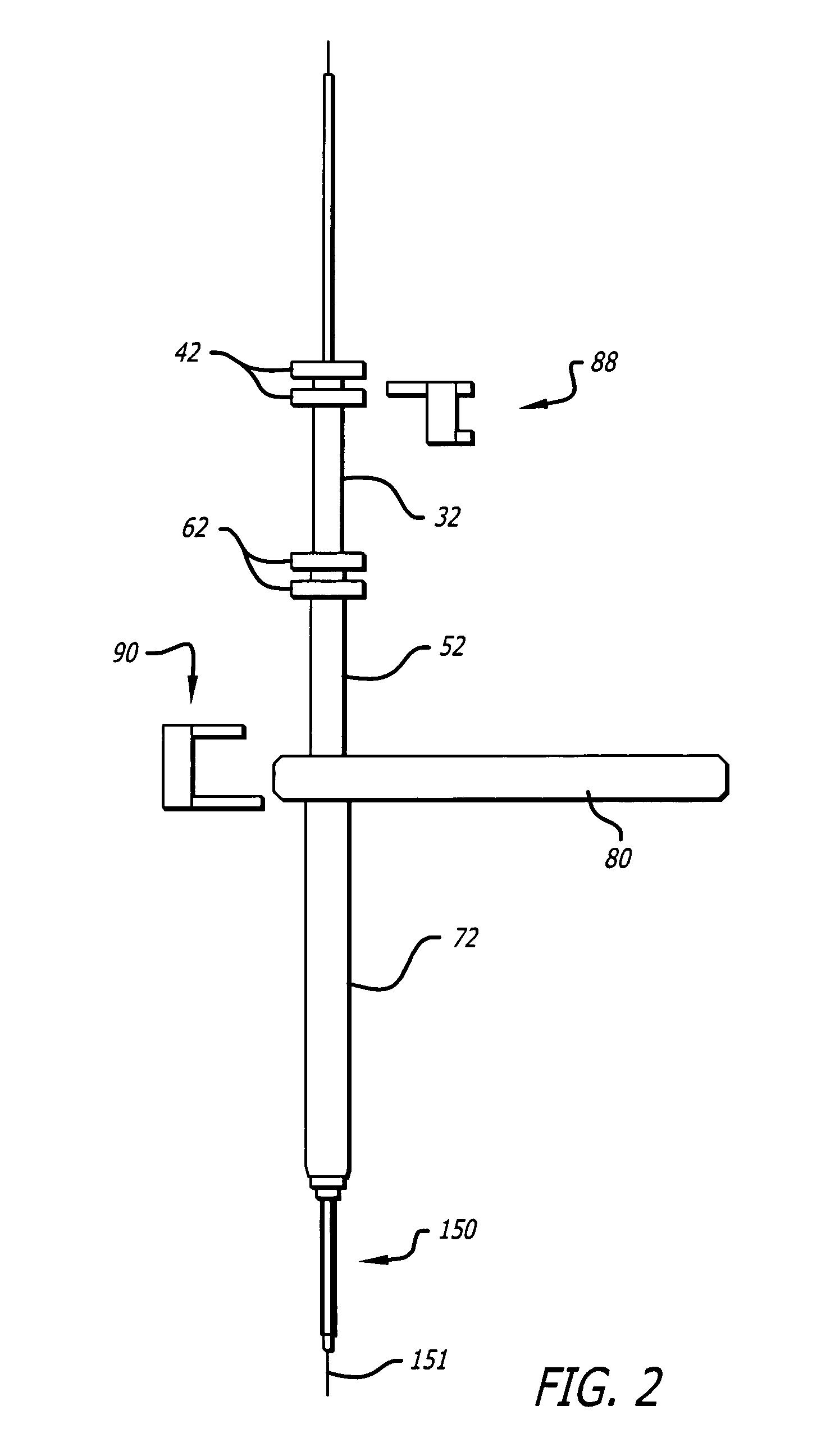
[0070] Referring to the drawings, which are provided for purposes of illustration and by way of example, the present invention provides for a telescoping dilation introducer for orthopedic surgery, the dilation introducer having a locked assembled configuration for initial placement of the dilation introducer against a patient's bone tissue to be treated, and an unlocked, collapsed configuration dilating the patient's soft tissue down to the bone tissue to be treated to a desired degree of dilation to permit minimally invasive surgical procedures on the patient's bone tissue to be treated.

[0071] While the invention will be described with specificity to a spinal fusion procedure, those skilled in the art will recognize that the apparatus and method of the art will recognize that the apparatus and method of the invention can also be advantageously used for procedures in which the dilation introducer can be brought up against other firm or solid structures in the body or introduced in...


PUM

PropertyMeasurementUnit
diameteraaaaaaaaaa
diameteraaaaaaaaaa
depthaaaaaaaaaa

Abstract

The dilation introducer has a locked assembled configuration for placement of the dilation introducer against a patient's tissue to be treated, and an unlocked, collapsed configuration for dilating the patient's soft tissue down to tissue to be treated. Dilator tubes are successively released and advanced to progressively expand the patient's soft tissue down to the bone tissue to be treated. The dilator tubes and a guide insert may include spikes for engaging bone tissue. The dilation introducer may include a light emitter disposed in a dilator tube. A telescoping expander sleeve is also provided.

Description

CROSS-REFERENCES TO RELATED APPLICATIONS [0001] This is a continuation-in-part of Ser. No. 10 / 911,215, filed Aug. 3, 2004.BACKGROUND OF THE INVENTION [0002] 1. Field of the Invention [0003] This invention relates to bone fixation devices, and more particularly relates to a dilation introducer for introducing a bone fixation device for orthopedic surgery, such as for vertebral fusion. [0004] 2. General Background and State of the Art [0005] Fusion of two adjacent vertebrae is a common surgical treatment for back injuries due to damage or defects in a spinal disc between two adjacent vertebrae, such as conditions due to a herniated disc or disc degeneration. The entire disc may be removed by a discectomy procedure, and may be replaced with bone or a bone substitute and / or cage in order to prevent collapse of the disc space between the adjacent vertebrae. Early techniques for stabilizing the adjacent vertebrae included application of a plate or a rod in conjunction with screws across t...

Claims


Application Information

Patent Timeline
17 Nov 2005
Publication
US20050256525A1
IPC
A01H1/00; A61B17/56; A61K48/00; C07H21/00; C07H21/02; C12N15/11; C12N15/113; C12N15/82; C12Q1/68; G01N33/48; G01N33/50; G16B20/20; G16B20/50
CPC
A61K31/713; C12N15/111; C12N15/113; C12N15/1135; C12N15/1136; C12N15/1137; C12N15/1048; C12N2310/14
Inventors
CULBERT, BRAD; OLMOS, FAUSTO