Clavicle repair device and orthopedic intramedullary fixation system

a technology of intramedullary fixation and clavicle, which is applied in the field of support devices, can solve the problems of affecting the healing and comfort of patients, affecting the design of im fixation devices, and unable to provide torsional resistance to bone fragments

a technology of intramedullary fixation and clavicle, which is applied in the field of support devices, can solve the problems of affecting the healing and comfort of patients, affecting the design of im fixation devices, and unable to provide torsional resistance to bone fragments

US20050027294A1Inactive Publication Date: 2005-02-03WOLL BIOORTHOPEDICS

Image

  • Clavicle repair device and orthopedic intramedullary fixation system
  • Clavicle repair device and orthopedic intramedullary fixation system
  • Clavicle repair device and orthopedic intramedullary fixation system

Examples


Embodiment Construction

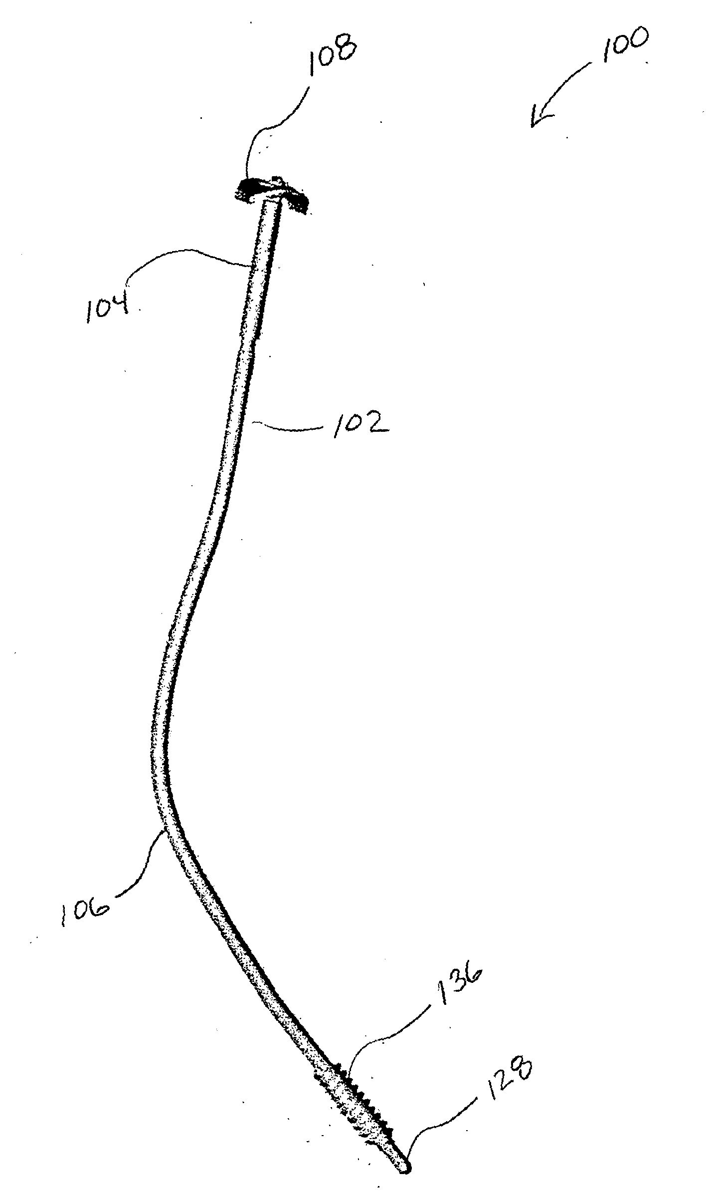
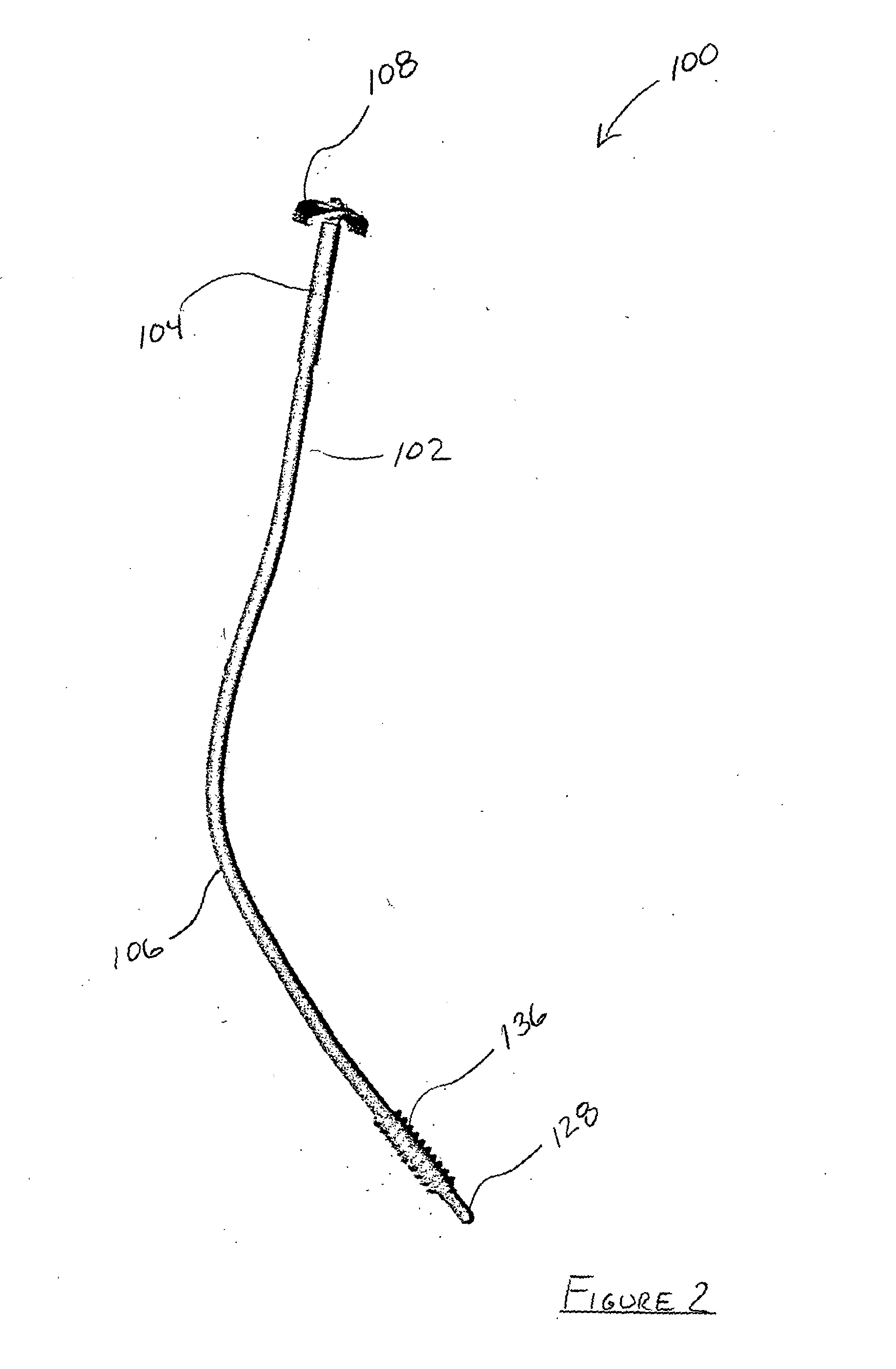
[0022] Referring to FIG. 2, an illustrative embodiment of a bone segment positioning device 100 is shown and includes a support shaft 102 having a collar shaft 104, a base shaft 106 and a stabilizing device 108. Referring to FIG. 3 and FIG. 4, collar shaft 104 is hollow and constructed from a malleable material and includes a collar shaft distal end 110, a collar shaft proximal end 112 and a stabilizer base 114. The stabilizer base 114 is disposed on collar shaft proximal end 112 and includes a spherically shaped outer surface 116 having a base diameter A and a plurality of key protrusions 118. Collar shaft distal end 110 includes a collar mating structure 120 which defines a collar shaft cavity 122 having an internal cavity wall 124 which includes a threaded portion 126. As disclosed herein, the term ‘distal’ refers to the element or portion furthest from a patients shoulder and the term ‘proximal’ refers to the element or portion closest to a patients shoulder.

[0023] Referring to...


PUM


Abstract

A bone segment positioning device including a base shaft, wherein the base shaft includes a base mating structure and an anchoring thread for securing the base shaft to a distal portion of a broken bone. Additionally, a collar shaft is provided, wherein the collar shaft includes a stabilizer base and a collar mating structure configured for associating with the base mating structure to secure the base shaft to the collar shaft. Moreover, a stabilizing device is provided, wherein the stabilizing device includes a collar configured for associating with the stabilizing base to secure the collar shaft with a proximal portion of the broken bone.

Description

FIELD OF THE INVENTION [0001] This invention relates generally to a support apparatus and more particularly to an intramedullary (IM) support apparatus for supporting broken bones wherein the IM support apparatus is constructed from a malleable material to be controllably configurable. BACKGROUND OF THE INVENTION [0002] Devices for stabilizing clavicle bones that have been fractured are well known in the art and stabilize the broken bone by providing an axial load force which keeps the fractured ends of the bone in contact with each other. Referring to FIG. 1, these IM fixation devices typically include anchoring threads disposed on an anterior portion of the IM fixation device and a bone re-association system disposed on a posterior portion of the IM fixation device, wherein the bone re-association system includes a threaded portion and a stabilizing nut. Axial re-association of the fractured portions of the bone is achieved by threading the IM fixation device through both portions...

Claims


Application Information

Patent Timeline
03 Feb 2005
Publication
US20050027294A1
IPC
A61B17/00; A61B17/72
CPC
A61B17/7208; A61B17/7225; A61B2017/00004; A61B17/7291; A61B17/7233
Inventors
WOLL, CHRISTIAN