Modular expandable display case

Inactive Publication Date: 2005-12-01
TENBRINK CARL EVAN
View PDF13 Cites 9 Cited by
  • Summary
  • Abstract
  • Description
  • Claims
  • Application Information

AI Technical Summary

Benefits of technology

[0011] Also provided is a longitudinal recess formed into the back extension for enabling the wall mounting screw heads to be countersunk into the back extension. This c

Problems solved by technology

While the modular configuration of the display case taught in U.S. Pat. No. 5,924,778 enables the horizontal and vertical expansion of

Method used


Image

  • Modular expandable display case
  • Modular expandable display case
  • Modular expandable display case

Examples


Example

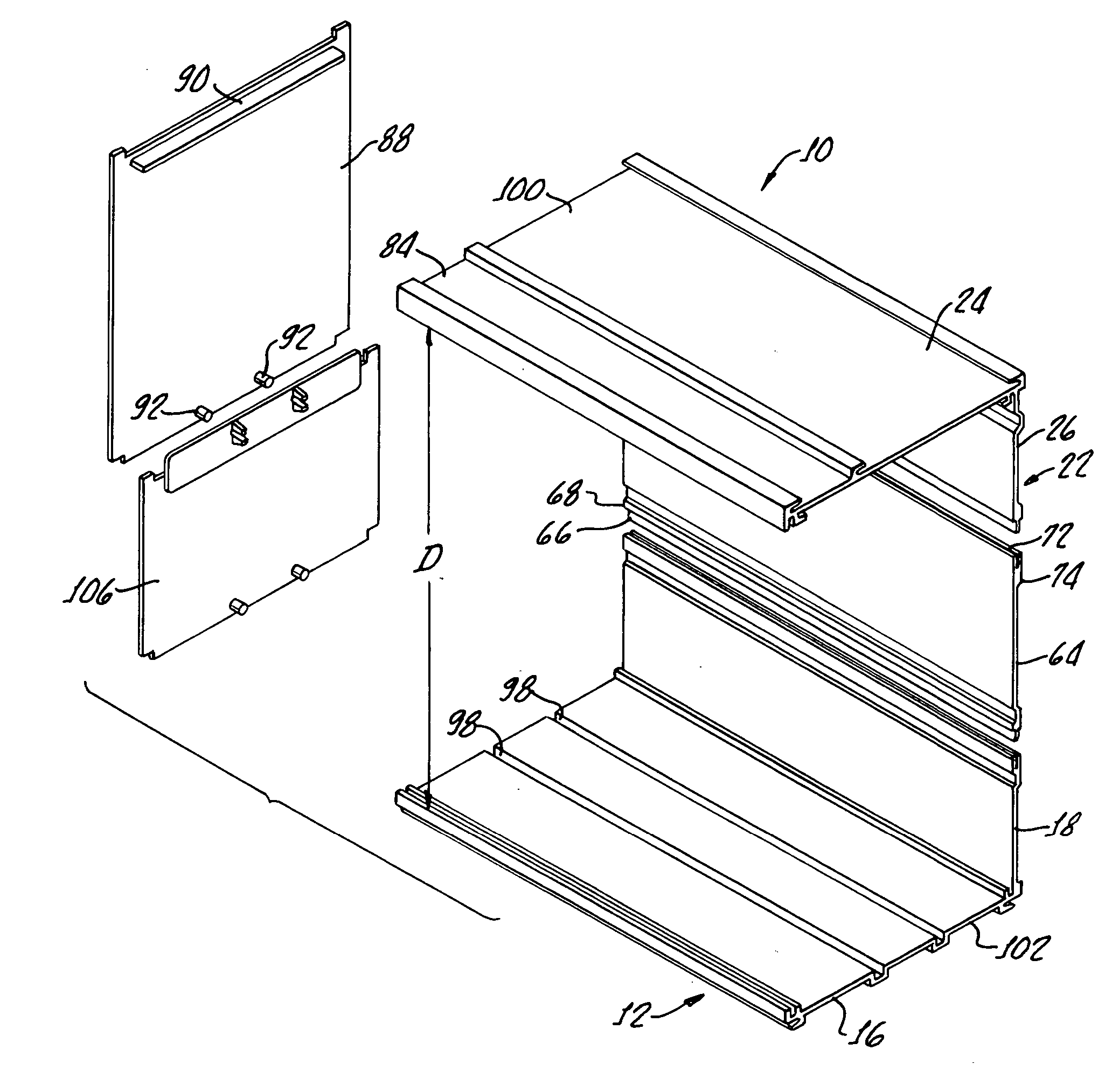
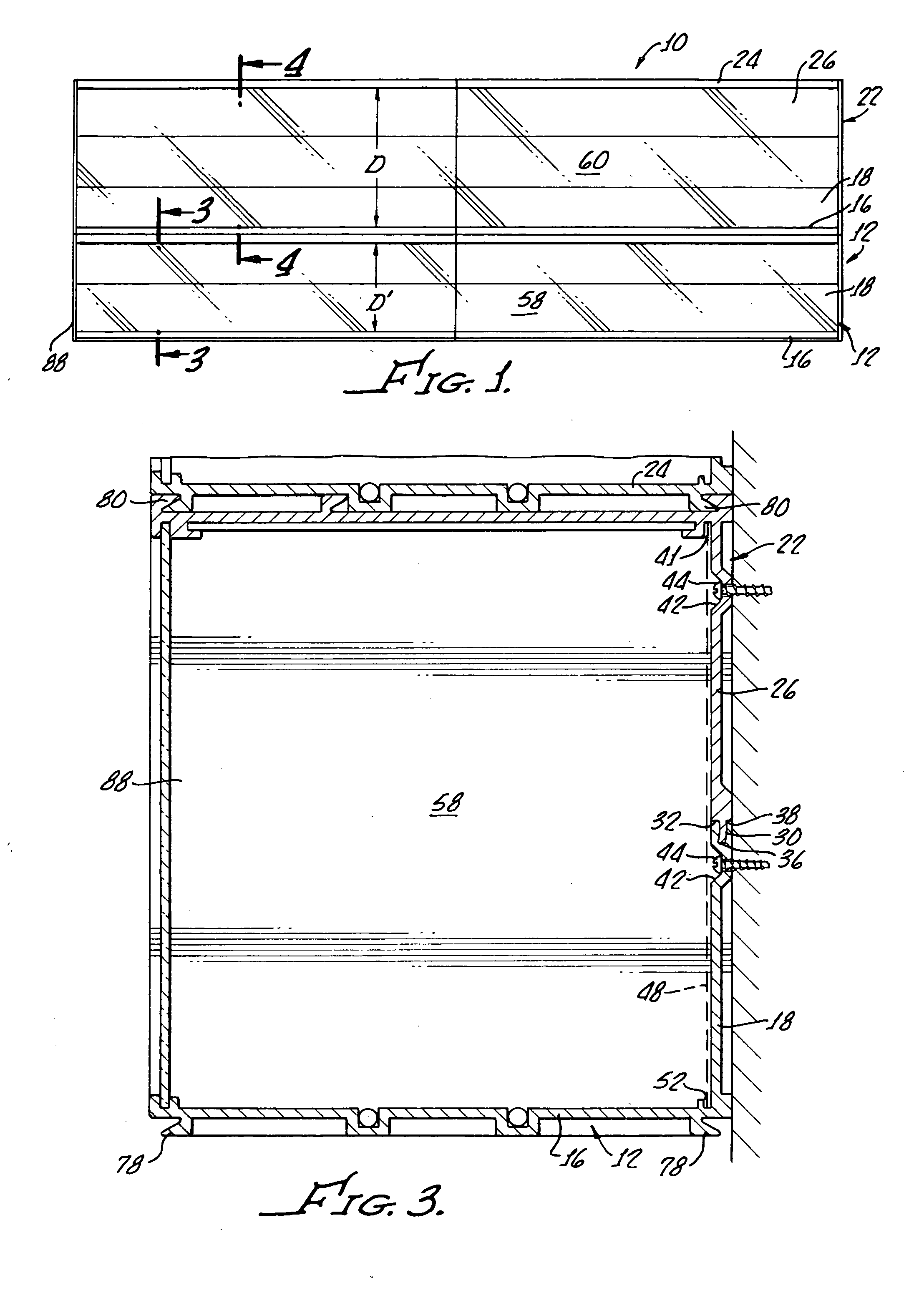
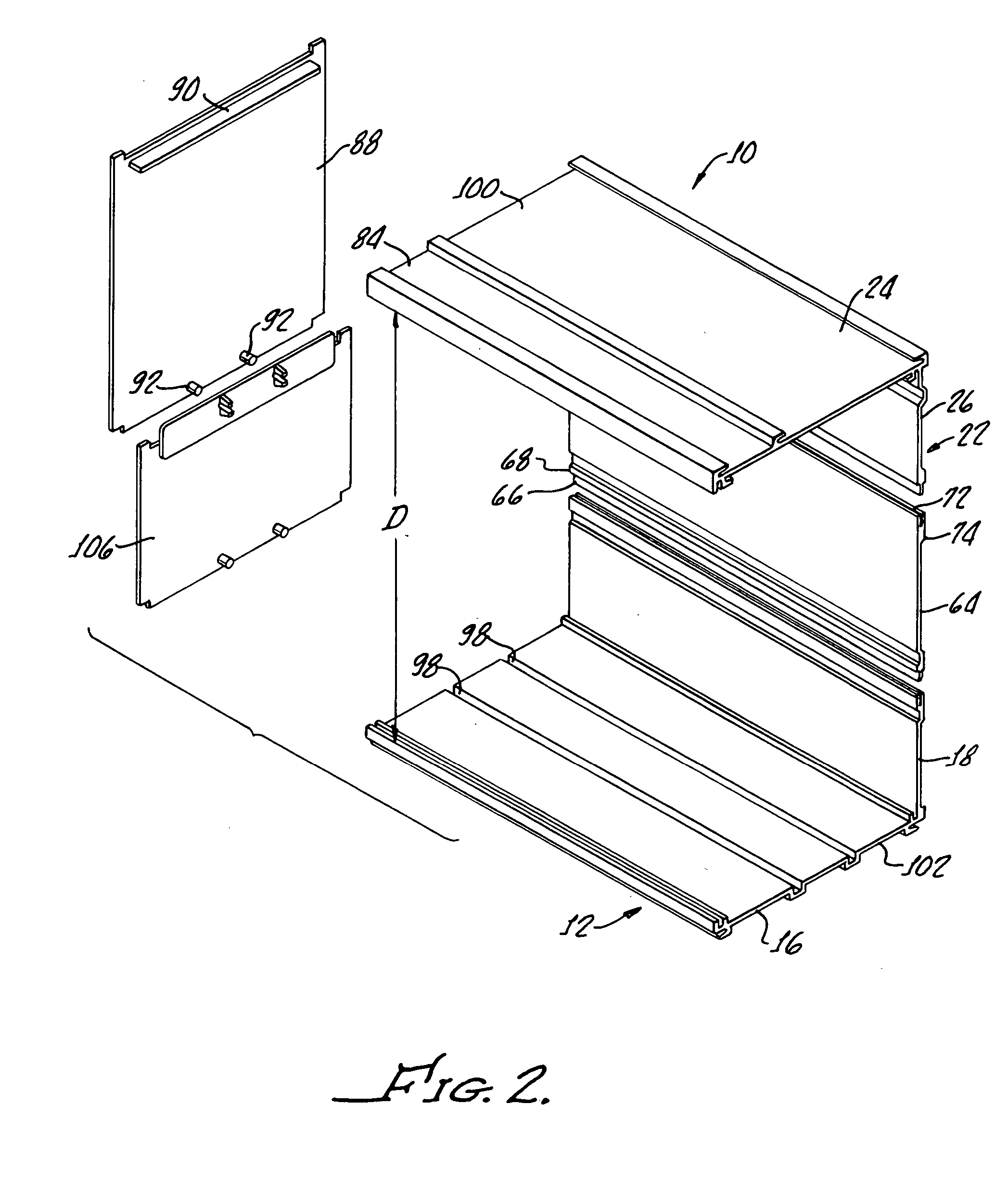
[0021] With reference to FIGS. 1 and 2, there is shown a display case 10 in accordance with the present invention illustrating L shaped bottom members 12 having bottoms 16 and backs 18 and L shaped top members 22 including tops 24 and backs 26.

[0022] The L shaped bottom member 12 and L shaped top member 22, as well as all other components of the present invention may be formed from any suitable material such as plastic or metal and manufactured in a conventional manner.

[0023] As most clearly shown in FIG. 3, a tongue 30 disposed on an edge 32 of the top member and depending back 26 provides engagement with a groove 36 disposed in an edge of the bottom member upstanding back 18 for not only enabling engagement of the bottom member 12 with the top member 22, but for enabling an extension of a distance between the bottom 16 and the top 24, as hereinafter discussed in greater detail.

[0024] It should be appreciated that while the tongue 30 is illustrated as being formed in an edge 32 ...


PUM

PropertyMeasurementUnit
Volumeaaaaaaaaaa
Lengthaaaaaaaaaa
Distanceaaaaaaaaaa

Abstract

A display case includes at least one L shaped bottom member having a bottom and an upstanding back along with an L shaped top member having a top and a depending back. A tongue is disposed on an edge of one of the backs and a groove is disposed on an edge of another of the backs for coupling the backs to one another. Back extensions are provided in order to extend a distance between the top and bottom upon assembly of the bottom member, top member and the back extension. End caps and end cap extensions are configured for engaging the bottom and top for closing ends of the bottom member and the top member.

Description

[0001] The present invention is generally related to display systems and is more particularly directed to a modular display case. [0002] Display cases are often used for presenting merchandise for retail purposes as well as for collectors for visibly showing their treasures. [0003] It is often desirable to provide a modular display case which is expandable horizontally and vertically in order to accommodate expanding numbers of items in a collection. [0004] One such modular display case is illustrated in U.S. Pat. No. 5,924,778 to TenBrink which is particularly suitable for displaying model trains and expandable, both horizontally and vertically to accommodate various trains and various types of other collectibles. [0005] While the modular configuration of the display case taught in U.S. Pat. No. 5,924,778 enables the horizontal and vertical expansion of the assembled case, the case is limited in not providing variable shelf height which can accommodate collectibles of differing sta...

Claims


Application Information

Patent Timeline
IPC IPC(8): A47B43/00A47B45/00A47B47/00A47B87/02
CPCA47B45/00A47B87/02A47B47/0066
Inventor TENBRINK, CARL EVAN
Owner TENBRINK CARL EVAN
Why Eureka
Try Eureka