
Liquid illuminator and assembly thereof

Inactive Publication Date: 2011-09-22
PULZ
View PDF5 Cites 11 Cited by
  • Summary
  • Abstract
  • Description
  • Claims
  • Application Information

AI Technical Summary

Benefits of technology

[0005]Accordingly, the present invention, in one aspect, is a lighting apparatus including a light source, a power source electrically connected to the light source, and a coupling portion connected to the light source. The coupling portion is flexibly compressible such that the light apparatus is easily inserted and secured within a space of a suitable size provided on the surface of the container.
[0006]In another aspect of the present invention, a liquid container assembly with illuminating light is disclosed. The liquid container assembly contains a liquid container and a light apparatus. The liquid container further includes a cavity formed on at least one surface. The light apparatus contains a light source, a power source electrically connected to the light source, and a coupling portion connected to the light source. The coupling portion is flexibly compressible such that the light apparatus is easily inserted and secured within the cavity in the liquid container.
[0007]There are many advantages to the present invention, one of which is that the flexible material used in the cover of the illuminator makes it suitable to adapt to various size of the space provided. In certain specific embodiment, the illuminator is adapted for simple insertion into a specially designed cavity created in the container. It makes the illuminator very easy to install and use. Certain implementations also allow for very simple mechanical and / or electrical design such that the illuminator can be very compact. A single size of the illuminator can be used for various sizes of bottles and containers as long as the size of the cavity to which it is inserted is appropriately adapted and shall be explained in the following specific implementation examples. The following invention can be applied to but not limited to wine bottle, drinking glass or any other types of liquid container.

Problems solved by technology

However, this method is only appropriate for an empty container and the candle cannot coexist with the liquid in the bottle.

Method used


Image

  • Liquid illuminator and assembly thereof
  • Liquid illuminator and assembly thereof
  • Liquid illuminator and assembly thereof

Examples


Embodiment Construction

[0019]As used herein and in the claims, “comprising” means including the following elements but not excluding others.

[0020]As used herein and in the claims, “couple” or “connect” refers to mechanical coupling or connection either directly or indirectly unless otherwise stated.

[0021]As used herein and in the claims, “cylinder” refers not only refers to geometrically defined cylinder but it may also refers to similar shapes or variations, for example, a conical shape, a cone shape with a flat top, or a ribbed cylinder.

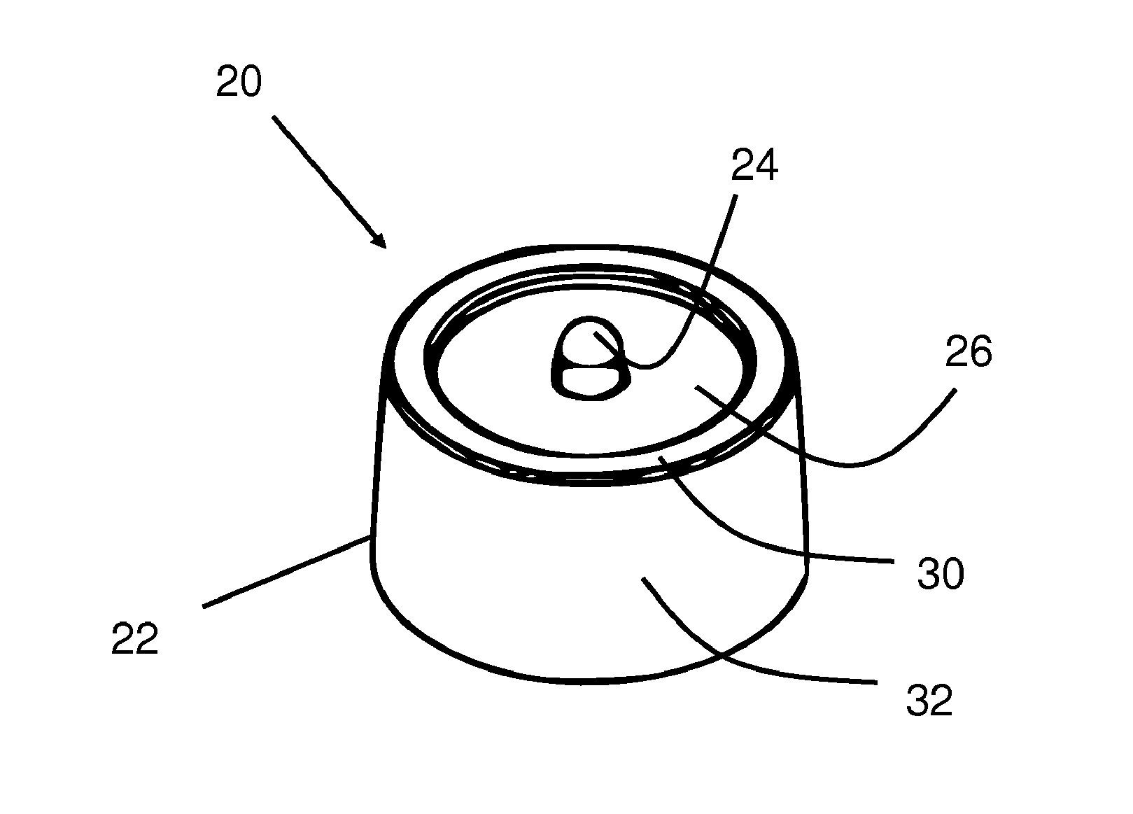
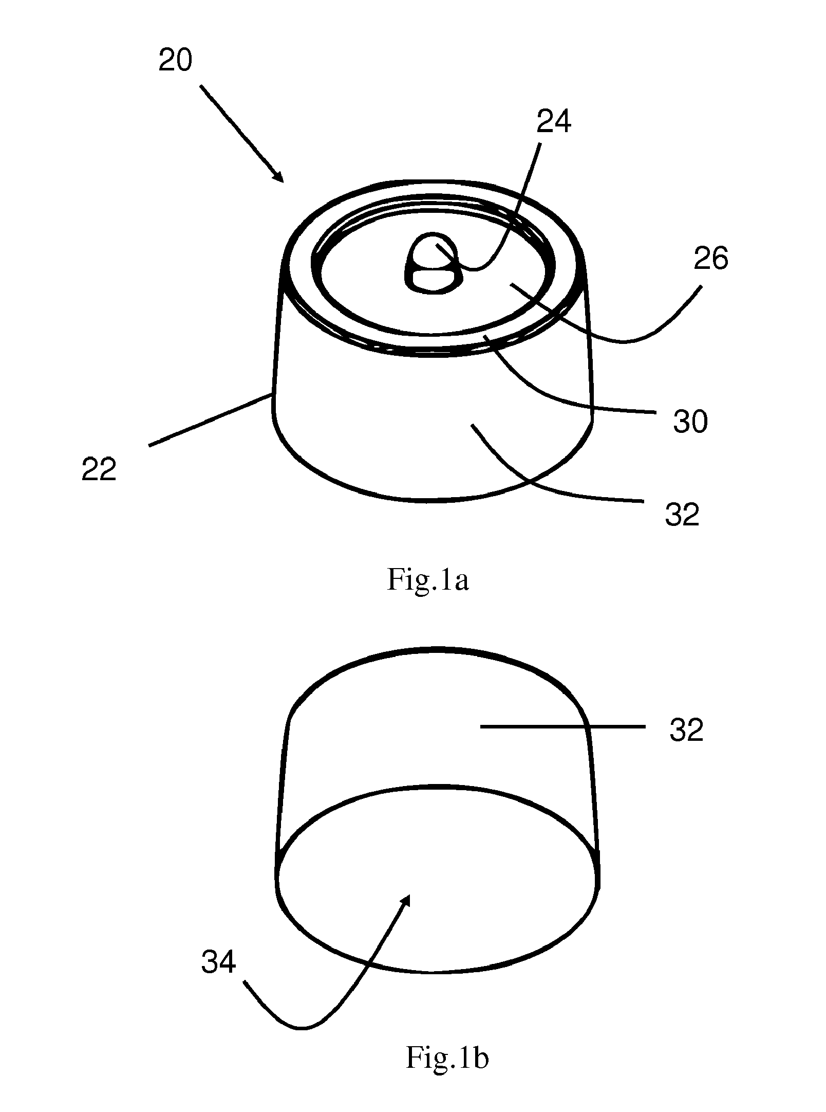
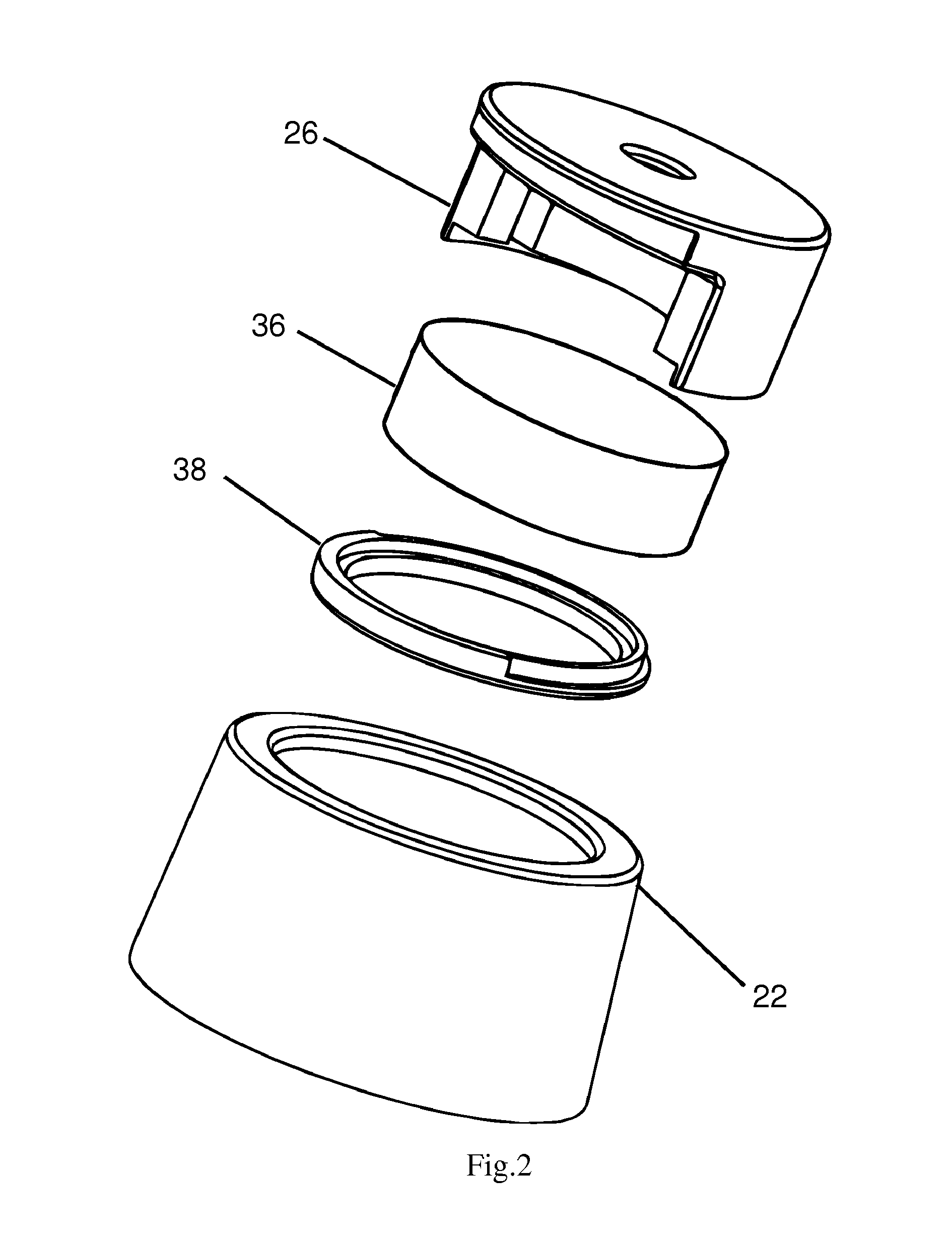
[0022]Referring now to FIGS. 1a and 1b, the first embodiment of the present invention is an illuminator 20 of a cylinder shape. The illuminator 20 includes a light source, a light cover 22, a light top 26 and a power source (not shown here). The light source is preferably a Light Emitting Diode (LED) 24. The power source is preferably a battery. The light cover 22 further includes a ring 30, a sleeve 32 and a bottom 34, all of which are formed as a single part. In this e...


PUM


Abstract

An illuminator (20) and a liquid container assembly including the illuminator are disclosed. The illuminator (20) includes a light source (24), a power source and a coupling portion (22). The coupling portion (22) is flexibly compressible such that the illuminator (20) is easily inserted and secured within a space of a suitable size provided on the surface of the liquid container. The illuminator (20) can be used in combination with various liquid container such as drinking glass or liquid bottle to provide illumination to the liquid in the container.

Description

TECHNICAL FIELD Field of Invention [0001]This invention relates to the field of a light apparatus in general and, in particular, to an illuminating apparatus that is used to illuminate the liquid contained in a container.BACKGROUND ART Background of Invention [0002]Of great concern to people when enjoying a drink is the mood and atmosphere which is especially important for alcoholic or other types of beverages. Producers are continuously adding decoration to the liquid bottle or drinking glass. One conventional method to add illumination is to add a base support to the container, which includes a light, and power supply.[0003]Another approach is to put a light source in the container, like a candle, for illuminating the container. However, this method is only appropriate for an empty container and the candle cannot coexist with the liquid in the bottle.DISCLOSURE OF INVENTION Summary of Invention [0004]It is an object of the present invention to provide a novel container illuminator...

Claims


Application Information

Patent Timeline
IPC IPC(8): F21V33/00
CPCA47G19/2227A47G2019/2238B65D2203/12B65D23/12B65D23/00
Inventor VAGNBY, MARCUS JONBY
Owner PULZ
Learn More