
Plastic bag and method

Inactive Publication Date: 2006-09-26
HONSTRATER RICHARD A
View PDF13 Cites 10 Cited by
  • Summary
  • Abstract
  • Description
  • Claims
  • Application Information

AI Technical Summary

Benefits of technology

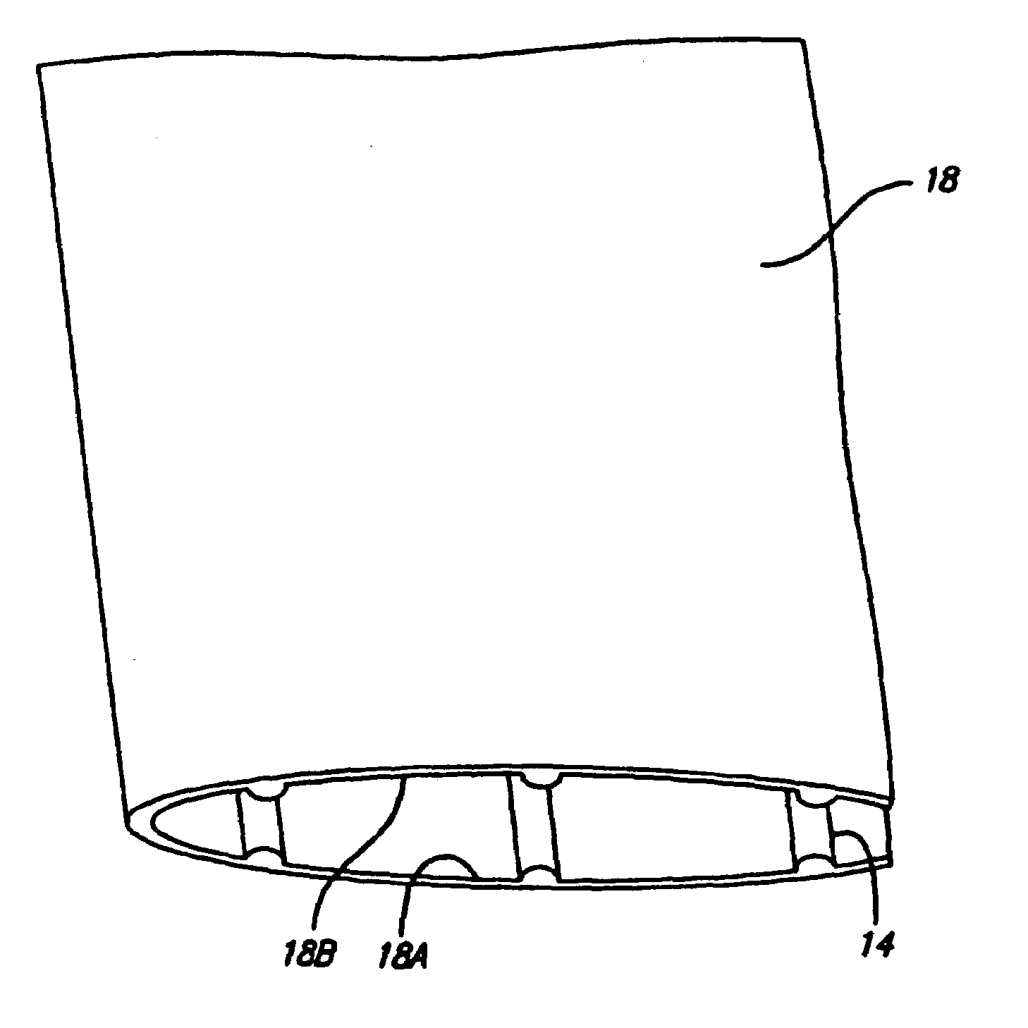
[0012]The present invention provides advantages in the respect of the foregoing problems. During extrusion of the bag, a series of longitudinal ribs are provided integrally with the interior of the bag. These longitudinal ribs provide added volume to the bag and added surface area to the inside of the bag. Consequently, more of the volatile corrosion inhibitor (VCI) can be stored and there is a larger surface area over which to outgas resulting in a greater volume of the VCI gas introduced inside the bag over a shorter time as well as availability of VCI over a longer time. Thus the invention lies in a method of enhancing the storage volume and consequently the rate and time period of outgassing of the VCI by providing longitudinal ribs which increase the total volume of the bag and the interior surface area of the bag.
[0014]Also, the longitudinal ribs allow the product to be inserted into the bag more easily by reducing friction and preventing snagging of corners or other sharp portions of the product on the bag's interior surface.
[0015]Also, the ribs prevent any portion of the bag from clinging to a flat surface, such as a printed circuit board.

Problems solved by technology

Also, such bags may have an antistatic material mixed into the raw material before it is formed and, therefore, contained in the volume of the bag, to discharge static electricity which could damage sensitive electronic components.
With the miniaturization that has occurred in the electronic industry, contamination has become a huge problem.
This can cause a problem in some packages where the geometry of the metal part could expose a smooth side of the metal to contact the smooth plastic.
The attraction between two smooth surfaces (van der Waals forces) can cause sticking and / or staining of the metal surfaces.
Rough surfaces are not desirable because of abrasion.
Corrosion develops in these areas and is at times a serious problem.
Further, there is, in some cases difficulty in inserting the product into the bag due to the surface friction between the bag and the product, or possible snagging of the product on the bag's interior surface.
Also, bags which have flat surfaces may cling to the flat surface of a printed circuit board which can be detrimental to that portion of the printed circuit board.

Method used


Image

  • Plastic bag and method
  • Plastic bag and method
  • Plastic bag and method

Examples


Embodiment Construction

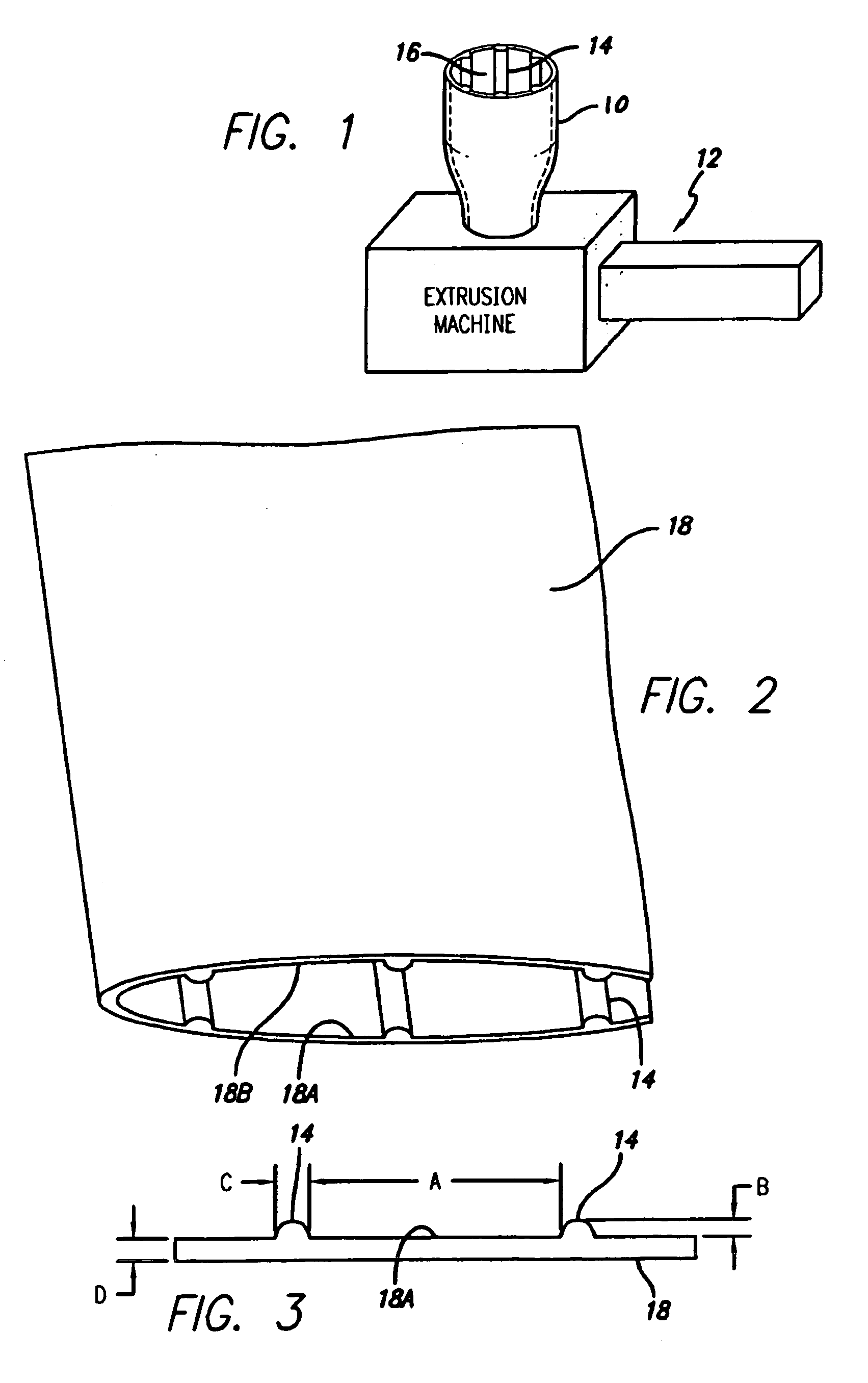
[0021]FIG. 1 shows in partial schematic form the extrusion of a bag. Exiting from the extrusion machine 12 the continuous tube of extrusion product 10 will be made into bags. The extrusion tube 10 will be laid flat in a roll or sent directly in the laid flat condition to the subsequent procedures. Those procedures include forming individual bags by cutting and sealing to have a sealed bottom and an open top, with the ribs of the present invention extending from top to bottom of the bag. The extrusion process is conventionally performed to provide a tube of plastic, which is continuously formed, and laid into a nip roll. It is then further processed to form bags. The extrusion machine is shown schematically at 12. According to the present invention the extrusion product 10 has ribs 14 on the interior surface 16, which will be the inside of the bag.

[0022]Referring to FIGS. 2 and 3 the ribs 14, are spaced apart by the dimension A, have a height dimension B and a thickness dimension C.

[...


PUM


Abstract

A system and method for preparing a plastic bag especially useful for carrying electronic products by extruding spaced apart ribs onto the interior surfaces so that the bag volume is greater, so that a greater amount of VCI or anti-static material can be carried in the bag volume and providing greater surface area for outgassing of the VCI into the bag interior. The ribs also facilitate insertion of items into the bag and prevent clinging of the bag interior surface to flat portions of the product carried therein.

Description

RELATED APPLICATIONS AND PATENTS[0001]This application is a continuation of application Ser. No. 10 / 003,398 filed on Oct. 22, 2001 now U.S. Pat. No. 6,591,980 which is a continuation of application Ser. No. 09 / 344,471 filed Jun. 25, 1999 now U.S. Pat. No. 6,321,907 the entire content of all of which is incorporated herein by reference.FIELD OF THE INVENTION[0002]This invention relates to plastic bags.BACKGROUND OF THE INVENTION[0003]Plastic bags are used to contain electronic products. Those electronic products often need very careful handling, such as in clean rooms to avoid contamination. Also, the bags in which the products are to be contained must be appropriately manufactured so as to not introduce contamination. There are also treatments introduced to the bag during its manufacture to benefit the product to be contained. One such treatment is a volatile corrosion inhibitor chemical mixed into the bag raw material before it is formed so that it is contained in the volume of the...

Claims


Application Information

Patent Timeline
IPC IPC(8): B31B19/00B65D33/00B65D33/02B65D81/26
CPCB65D33/00B65D81/266B65D33/02B65D33/007
Inventor HONSTRATER, RICHARD A.
Owner HONSTRATER RICHARD A
Learn More