Spreading apparatus for flowable materials

Inactive Publication Date: 2006-01-12
BILLY STAR HLDG
View PDF13 Cites 14 Cited by
  • Summary
  • Abstract
  • Description
  • Claims
  • Application Information

AI Technical Summary

Benefits of technology

[0015] In the spreading apparatus, the reservoir chamber is preferably attached to the pad retaining means. More preferably, the reservoir chamber is pivotally attached to the pad retaining means to permit pivoting of the reservoir chamber frontwards and backwards. Such a configuration facilitates keeping the pad retaining means parallel to the surface thereby ensuring that the pad is always in full contact with the surface. This leads to more uniform spreading of the flowable material and accommodates operators of various heights.
[0016] The pad retaining means retains the spreader pad in a removable fashion. Thus, the pad may be removed and replaced without replacing the pad retaining means or the spreading apparatus. Preferably, retention of the spreader pad is accomplished without the use of springs and/or clips nor any other ancillary element requiring operator manipulation. In this way, the pad may be removed and replaced more easily and the spreading apparatus is less complicated to build and maintain.
[0017] In one embodiment, the spreader pad is retained by frictional engagement of the pad within the pad retaining means. The pad retaining means may comprise a tight tolerance channel having two walls between which the spreader pad is retained by frictional engagement of the pad with the inside surfaces of the two walls. The channel may be closed at the top to prevent the pad from slipping too far up between the walls. Part of the spreader pad extends below the pad retaining means so that the spreader pad rather than the pad retaining means contacts the surface. Each or either end of the channel may be further extended at a right angle to form an U-shaped or an L-shaped channel. In particular, a U-shaped channel with a corresponding U-shaped spreader pad helps keep flowable material confined to the region behind the spreader pad when the flowable material is dispensed from the gate. In this embodiment, the spreader pad may comprise an elongated resilient foam member

Problems solved by technology

Such operations are labour-intensive and also tend to be somewhat messy unless the operator is particularly careful,

Method used


Image

  • Spreading apparatus for flowable materials
  • Spreading apparatus for flowable materials
  • Spreading apparatus for flowable materials

Examples


Embodiment Construction

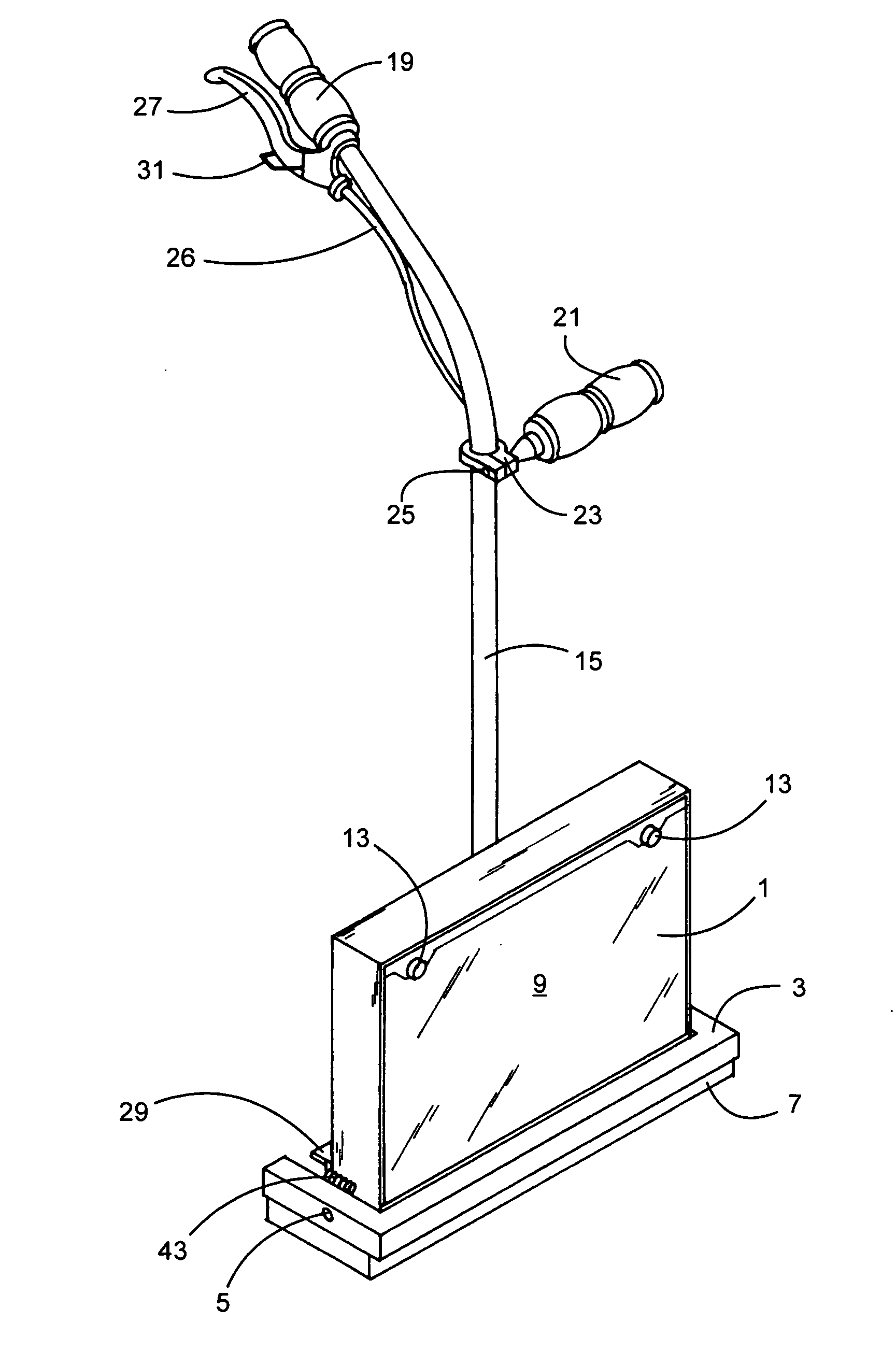
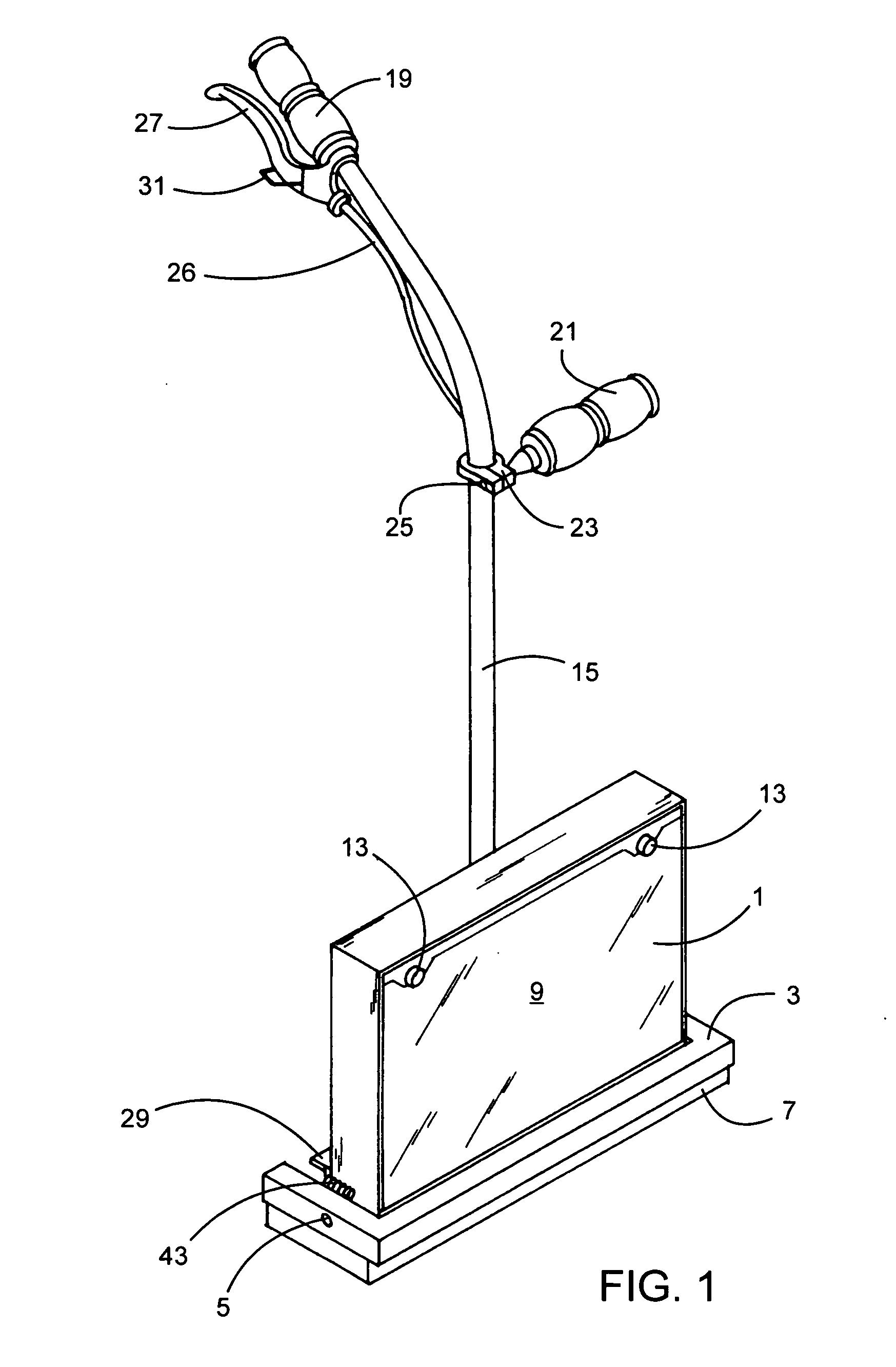
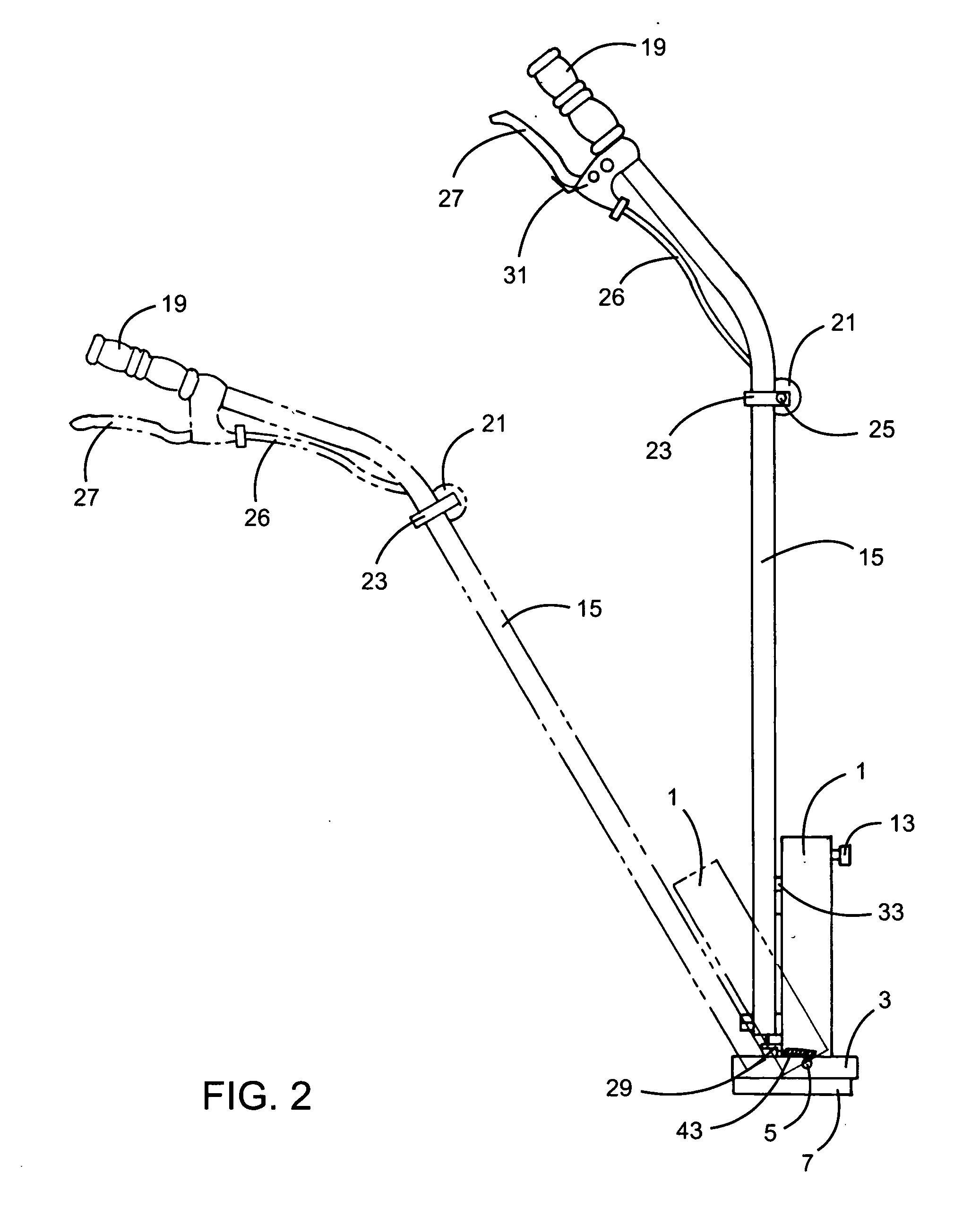
[0037] Referring to FIGS. 1-8, an embodiment of a spreading apparatus of the present invention is illustrated. A reservoir chamber 1 in the shape of a rectangular prism having a top face, a bottom face, a front face, a back face and two side faces is pivotally attached to a U-shaped pad retaining means 3 by means of two bolts 5. Only one of the two bolts 5 is shown, the other bolt corresponding in position to the one bolt but located on the other side. As best seen in FIGS. 5 and 6, the U-shaped pad retaining means 3 comprises a tight tolerance channel having two arms each arm extending at right angles from each end of a cross-member. A U-shaped foam spreader pad 7 is inserted in the channel and is held in place by frictional engagement of the pad within the channel of the pad retaining means 3.

[0038] The front face of the reservoir chamber 1 is a transparent door 9 hinged at the bottom by a door hinge 11 running the width of the reservoir chamber (see FIGS. 5, 6 and 7 in particula...


PUM


Abstract

A spreading apparatus is provided for spreading flowable materials such as adhesives and/or sealants on a surface such as a floor and/or a wall. The apparatus has a pad retainer for retaining a removable spreader pad and a reservoir chamber for flowable material pivotally attached to the pad retainer to permit pivoting of the reservoir chamber frontwards and backwards. The reservoir chamber has an adjustable gate through which the flowable material may exit. The gate is proximal the bottom of the reservoir chamber and complementary to the width of the pad retaining means to permit more uniform spreading of the flowable material. A handle is attached to and extends from the reservoir chamber. The handle may pivot from side to side on the reservoir chamber and may be hollow to house a cable associated with the means for opening the gate. A system is also provided involving the spreading apparatus together with a removable spreader pad and a container containing the flowable material. The container is housed in the reservoir chamber and cooperates with the gate to permit the flowable material to exit the container and the reservoir chamber when the gate is open. The spreader pad comprises an elongated resilient foam member sufficiently thick to fit within and frictionally engage the pad retainer, and sufficiently high to extend below the pad retainer so that the spreader pad rather than the pad retainer contacts the surface when the spreader pad is retained by the pad retainer.

Description

FIELD OF THE INVENTION [0001] This invention relates to spreading apparatuses for flowable materials, in particular to spreading apparatuses for spreading flowable adhesives and / or sealants on a surface. BACKGROUND OF THE INVENTION [0002] A number of service industries in which a decorative or protective finish is applied to a surface employ an adhesive and / or sealant for that purpose. The adhesive and / or sealant must be spread uniformly as a thin coating on the surface. A particular industry with such a requirement is the installation of coverings on floors and / or walls. Coverings may be, for example, carpet, sheet plastic (e.g. vinyl), plastic tiles, ceramic tiles, composite strips and wood strips. [0003] Adhesives and sealants are generally supplied in a variety of containers of the type also generally used for paints. Thus, small quantities of a liter or part liter are supplied in metal cans with press-on lids, while larger quantities, e.g. 20 or 40 liters, are supplied in small...

Claims


Application Information

Patent Timeline
IPC IPC(8): A46B11/04A47L13/22
CPCA47G27/0487B05C11/028E04F21/20E04F21/02B05C17/10E04F21/241
Inventor LIVINGSTONE, DAVID E.PITMAN, ROBIN G.MATECHUK, RONALD W.
Owner BILLY STAR HLDG
Why Eureka
Try Eureka