Autofocus actuator

Active Publication Date: 2006-02-09
MITSUMI ELECTRIC CO LTD
View PDF5 Cites 121 Cited by
  • Summary
  • Abstract
  • Description
  • Claims
  • Application Information

AI Technical Summary

Benefits of technology

[0013] With the above-mentioned problems in mind, it is an object of the present invention to provide an autofocus actuator having a yoke that permits

Problems solved by technology

A need of such bending process reduces the yield rate or productivity of the springs.
This poses a drawback in that the number of parts of the actuator is increased.
Moreover, the front spring and the rear spring are of mutually different shape, which disadvantageously leads to an increased manufacturing cost of the springs.
However, the permanent magnets with such configuration are costly, thus the cost for the parts becomes higher.
In ad

Method used


Image

  • Autofocus actuator
  • Autofocus actuator
  • Autofocus actuator

Examples


Example

[0042] An autofocus actuator proposed by the present inventor and used as the premise of the present invention will be first described in detail with reference to the drawings attached.

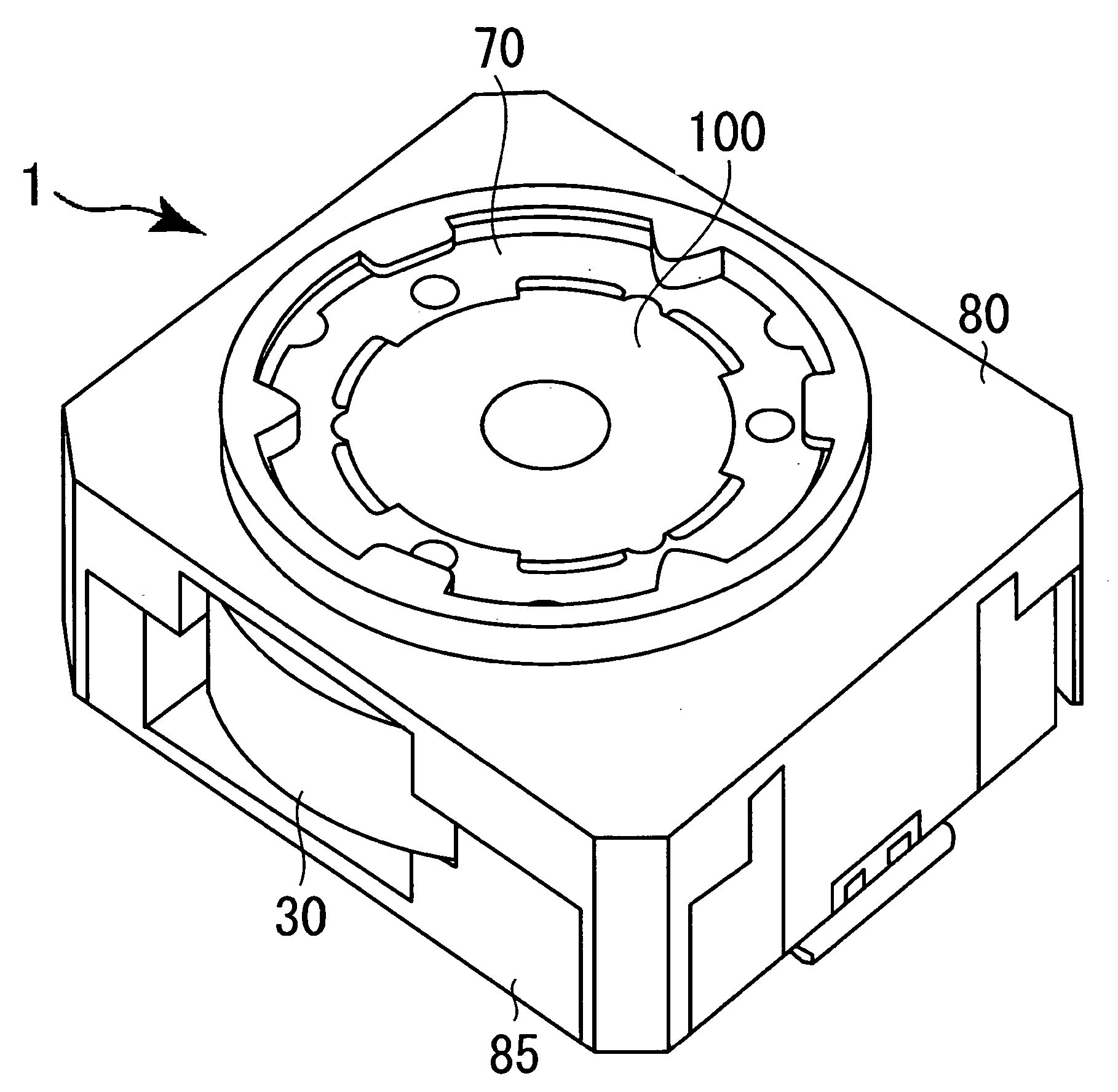
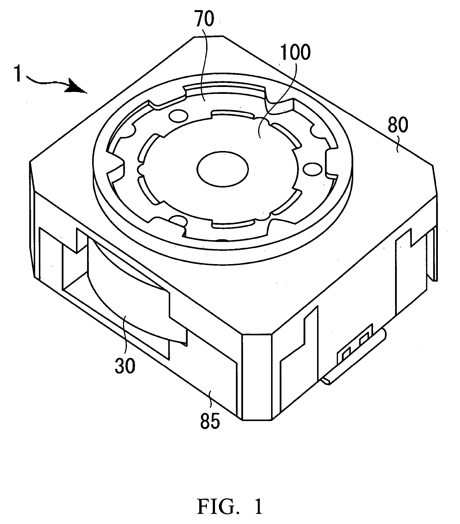
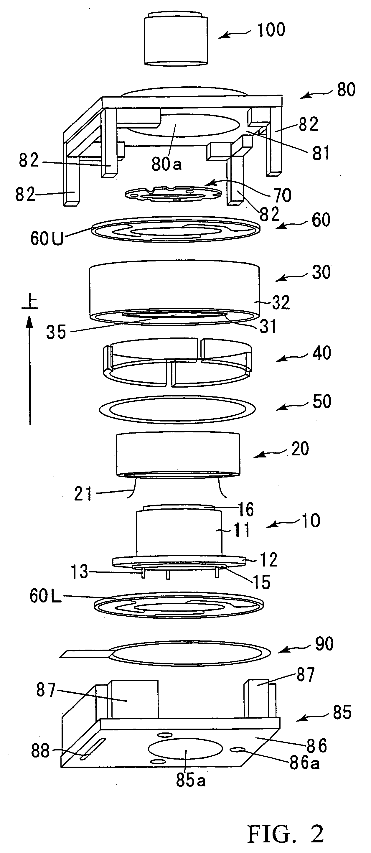
[0043] Referring to FIG. 1, there is shown perspective view showing the external appearance of the autofocus actuator. FIG. 2 is an exploded perspective view of the autofocus actuator shown in FIG. 1. FIG. 3 is a schematic cross-sectional view of the autofocus actuator shown in FIG. 1.

[0044] As shown in FIGS. 1, 2 and 3, the autofocus actuator 1, simply referred to as “actuator” hereinbelow, is generally composed of: a holder 10 including a hollow body portion 11 having one end to which a lens assembly 100 is attached, and a flange portion 12 provided along the perimeter of the other end of the hollow body portion 11; a coil 20 fixedly secured to the holder 10 in a spaced-apart relationship with the outer circumference of the hollow body portion 11; a cylindrical yoke 30 including an inner cylindric...


PUM


Abstract

An autofocus actuator 1 is provided with a yoke 300 that comprises an inner cylindrical portion 301 defining an insertion bore through which a hollow body portion of a holder is adapted to be received and an outer cylindrical portion 302 provided outside of the inner cylindrical portion 301 with a predetermined spacing left between the inner cylindrical portion 301 and the outer cylindrical portion 302 by a connecting portion, and the yoke 300 is constructed so as to receive a coil 20 in the space of a predetermined gap. The outer cylindrical portion 302 is formed into a generally polygonal cylindrical shape and inner surfaces of the outer cylindrical portion 302 define a plurality of magnet mounting surfaces each having a planar shape. A generally flat plate shape permanent magnet 41 is mounted on each of these magnet mounting surfaces 303. By the use of such a flat plate shape permanent magnet 41, it becomes possible to reduce a manufacturing cost and also possible to easily align and assemble the permanent magnets 41.

Description

BACKGROUND OF THE INVENTION [0001] 1. Field of the Invention [0002] The present invention relates to an autofocus actuator, and more specifically to an autofocus actuator that can be employed in digital cameras or other small-sized electronic apparatuses equipped with a camera, e.g., cellular phones. [0003] 2. Description of the Related Art [0004] In digital cameras, an actuator that can displace a lens in an optical axis direction is employed for the sake of autofocusing and zooming operations. This type of actuator is adapted to displace the lens in the optical axis direction by virtue of an interaction between the magnetic field generated by the electricity flowing through a coil and the magnetic field of a permanent magnet. In recent years, a need exists for the function of autofocus even in a camera mounted to cellular phones, because the number of pixels of a picture-taking element for use in the cellular phone camera tends to increase up to the order of mega pixels greater th...

Claims


Application Information

Patent Timeline
IPC IPC(8): G08B3/00
CPCG02B7/08H04N5/2254G03B13/36G03B3/10
Inventor OSAKA, TOMOHIKO
Owner MITSUMI ELECTRIC CO LTD
Why Eureka
Try Eureka