
Endoscope objective lens and method of assembly

Active Publication Date: 2011-02-08
INTEGRATED MEDICAL SYST INT INC
View PDF9 Cites 7 Cited by
  • Summary
  • Abstract
  • Description
  • Claims
  • Application Information

AI Technical Summary

Benefits of technology

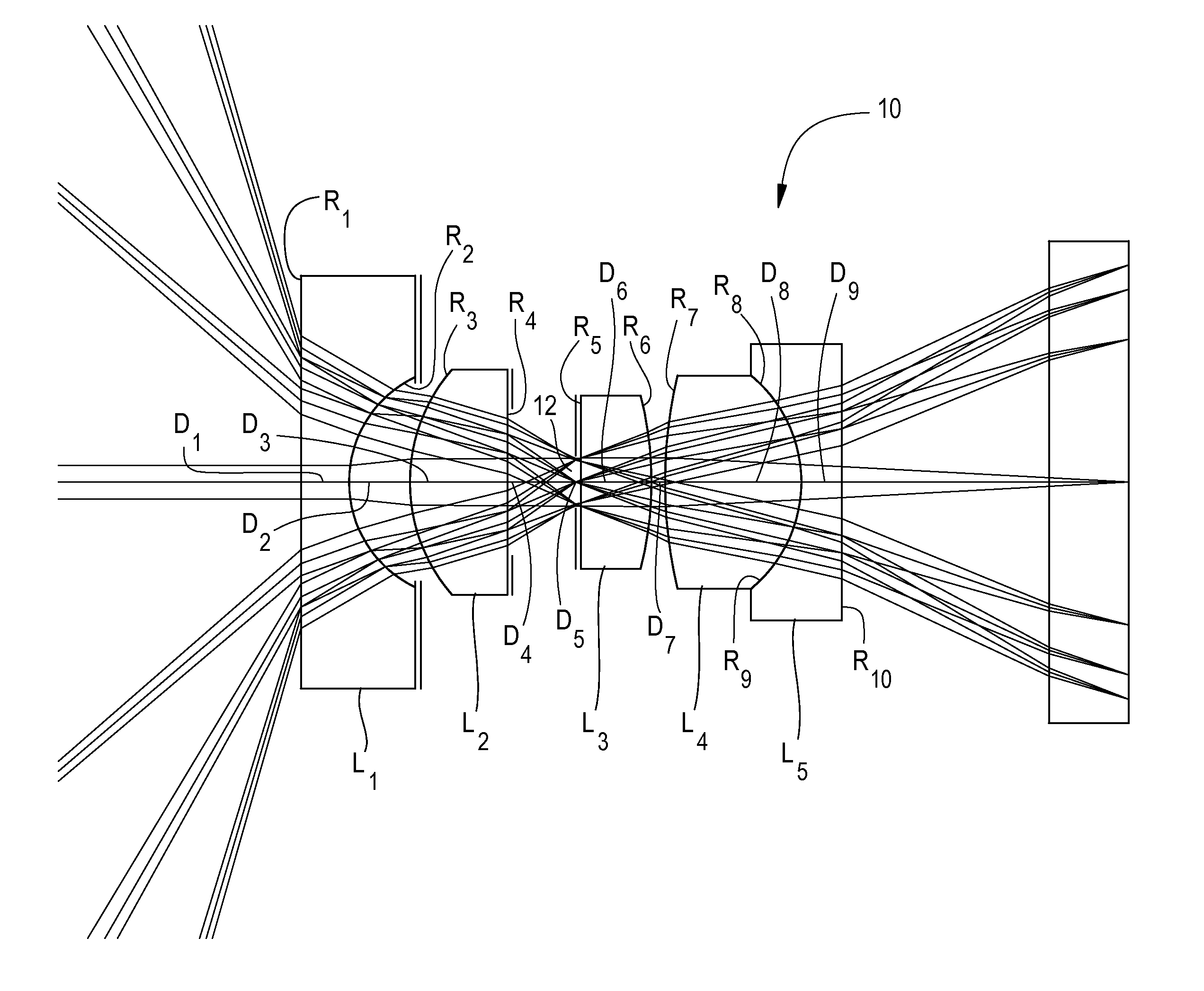
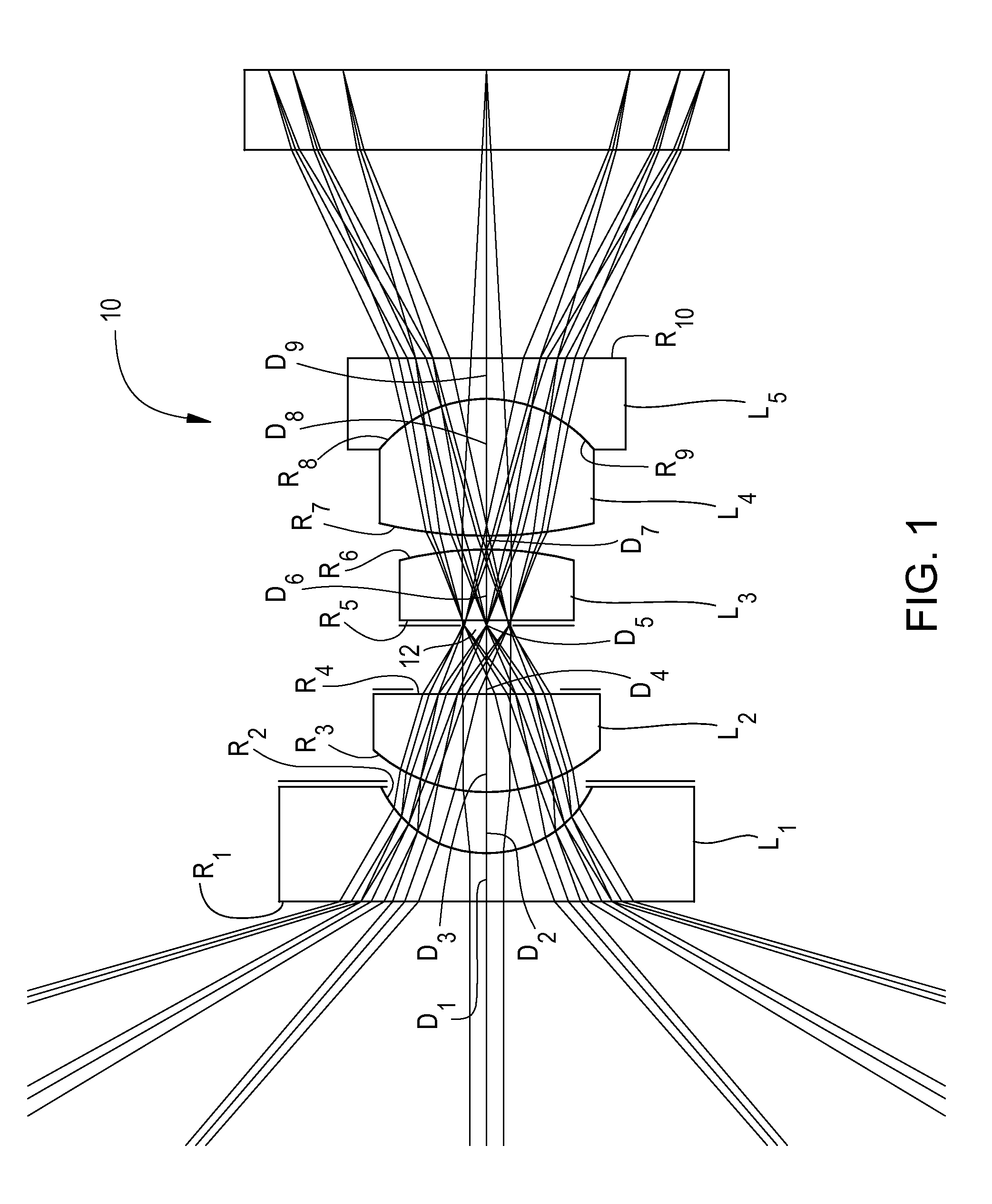
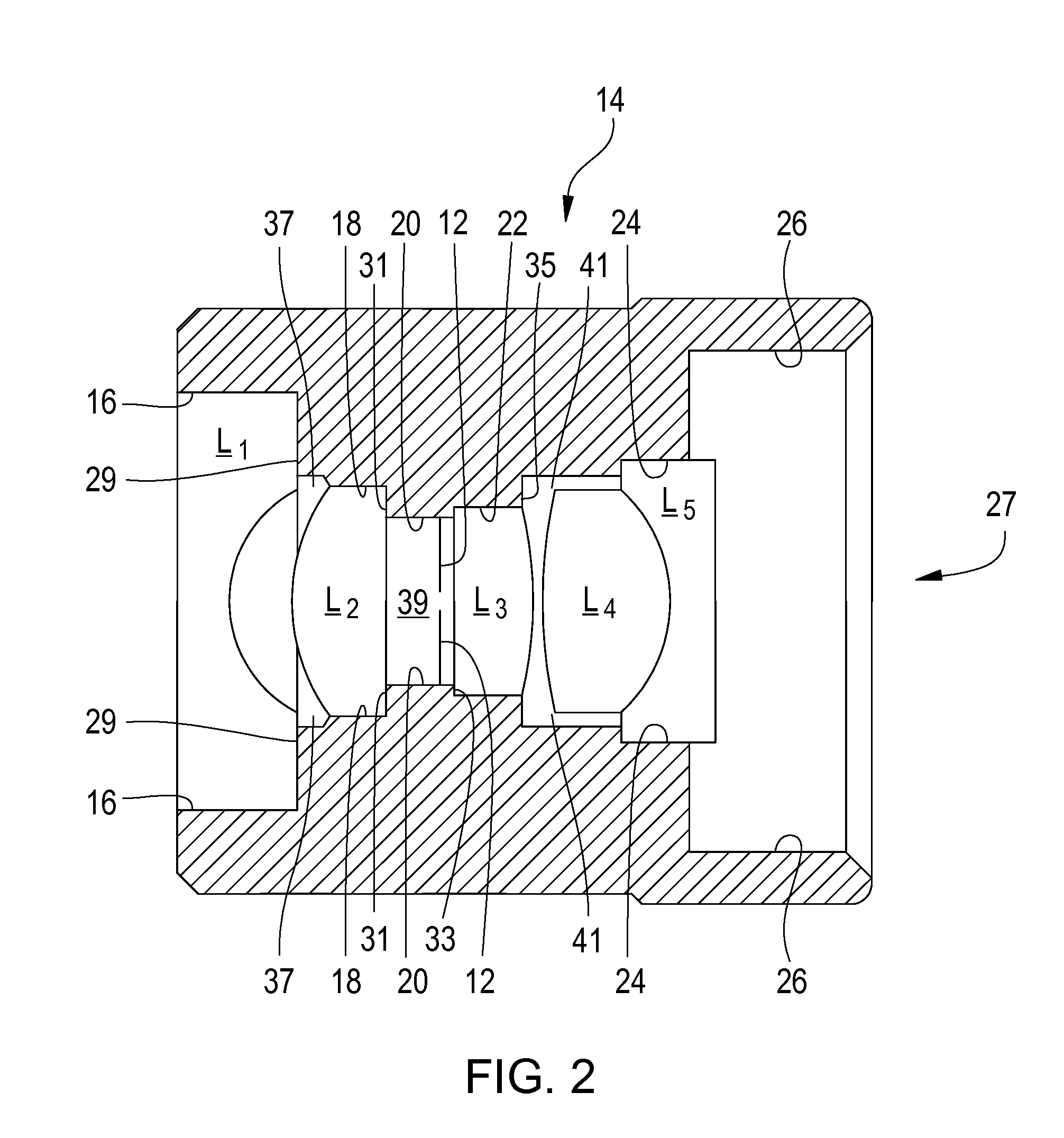
[0006]The present invention is directed to a wide field video endoscope objective lens and method of assembly including the following four groups with five lenses: a plan concave lens with the concave surface facing the image side, a plan convex lens with the convex side facing the object side, an aperture stop, a plan convex lens with the convex side facing the image side and an achromatic lens composed of bi-convex lens cemented to a plan concave lens, a mechanical housing containing all the image forming elements and the aperture stop, a centering member which is at first centered over a photosensitive area of a video chip and bonded to the surface of a video chip cover glass for holding the mechanical housing with the lenses centered to the photosensitive area, and a retainer sleeve which slides over the centering member and is glued to the centering member and the housing of the video chip. The optical and mechanical design and the method of assembly of the present invention result in a compact objective lens for video endoscopes having a high optical performance. The construction is easily aligned and assembled, robust and withstands day to day rough handling in the hospital environment.

Problems solved by technology

Making this task more difficult is that video chips require an objective lens with a wide field of view and an even performance over the full chip format.
That is because flexible video endoscopes operate in very narrow body cavities where orientation within these narrow body cavities is difficult.
Any surface imperfection close to the video chip can cause a spot to appear within the image area.

Method used


Image

  • Endoscope objective lens and method of assembly
  • Endoscope objective lens and method of assembly
  • Endoscope objective lens and method of assembly

Examples


examples

[0036]Two objective lens designs were used with a chip format of 1.8 mm×2.4 mm with a diagonal of 3 mm and optimized to work best with a cover glass of 0.3 mm to 0.5 mm on the photosensitive area of a video chip. The radius of curvature R (mm) of each lens surface, center thickness of each lens and air gap between the lenses D (mm), and values of refractive index Nd and Abbe number Vd of each lens at the d line of the two endoscope objective lens design are listed in Tables 1 and 2. The Abbe number is a measure of the degree to which light is dispersed when entering a lens. The lower the Abbe number, the greater the dispersion of light, which causes chromatic aberration (color fringing) in the periphery of the lens.

[0037]Note that numbers in the table indicate the order from the object side (the fifth surface is a stop) as depicted in FIG. 1.

[0038]

TABLE 1Radius of curvature (mm)Center thickness (mm)Nd / VdR1 = InfinityD1 = 0.301.881 / 41.0R2 = 0.72D2 = 0.38AirR3 = 1.06D3 = 0.601.697 / 55....


PUM

PropertyMeasurementUnit
Fractionaaaaaaaaaa
Lengthaaaaaaaaaa
Distanceaaaaaaaaaa

Abstract

A wide field video endoscope objective and method of assembly the objective including four groups with five lenses, a mechanical housing containing the entire image forming elements, a aperture stop, a centering member and a retainer sleeve. The centering member is at first centered over the photo sensitive area of the chip and bonded to the surface of the cover glass. The retainer sleeve slides over said centering member and is glued to the centering member and the housing of the video chip. The objective housing with the optical elements is screwed on the centering member to adjust for focusing.

Description

FIELD OF INVENTION[0001]The present invention relates to an objective lens and method of assembly. More particularly, the invention relates to a compact, wide field video endoscope including an objective barrel containing a set of five image forming lenses and a centering assembly readily connectable between the objective barrel and a video chip for optically aligning the image forming elements with the video chip.BACKGROUND OF THE INVENTION[0002]Many endoscopic applications require an endoscope that is sufficiently flexible for allowing the endoscope to travel through the curved passageways inside the body. For decades, physicians have used endoscopes that rely on flexible image and illumination bundles with loose glass fibers. In a short rigid portion at the tip of such endoscopes is an objective lens connected to the image bundle. The length of this rigid tip is crucial for the flexibility and maneuverability of the endoscope inside the body. Various types of objective lenses for...

Claims


Application Information

Patent Timeline
IPC IPC(8): G02B21/02G02B9/34G02B9/60
CPCG02B23/243G02B23/2484H04N5/2254Y10T29/49826H04N2005/2255G02B7/021H04N23/555
Inventor BODOR, PETER PALZOBEL, JURGENLULLIE, DANIEL
Owner INTEGRATED MEDICAL SYST INT INC
Learn More