

Optical system and image pickup apparatus having the same
- Summary
- Abstract
- Description
- Claims
- Application Information
AI Technical Summary
Benefits of technology
Problems solved by technology
Method used
Image

Examples
example 1
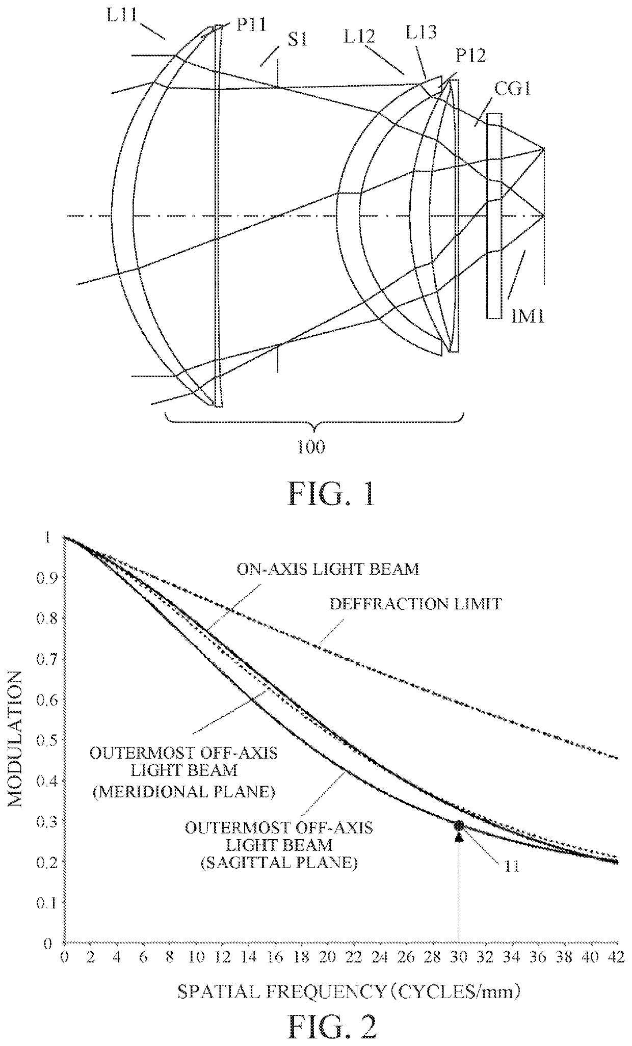
[0035]FIG. 1 is a sectional view of an optical system 100 according to this example. The optical system 100 is an infrared optical system having a focal length of 18 mm and an F-number of 0.8. The infrared optical system, as used herein, is an optical system that images an object with light having a wavelength of 8 μm or longer. The optical system 100 includes, in order from the object side to the image side, a first lens L11 having a positive refractive power and made of a silicon material, a thin aspherical plate (optical element) P11 made of a silicon material and having an aspherical portion with a thickness that gradually increases from the center to the periphery (or with a thickness that monotonously increases from the on-axis to the outermost off-axis in the section including the optical axis), a diaphragm (aperture stop) S1, a second lens L12 having a positive refractive power and made of a silicon material, a third lens L13 having a positive refractive power and made of a ...
example 2
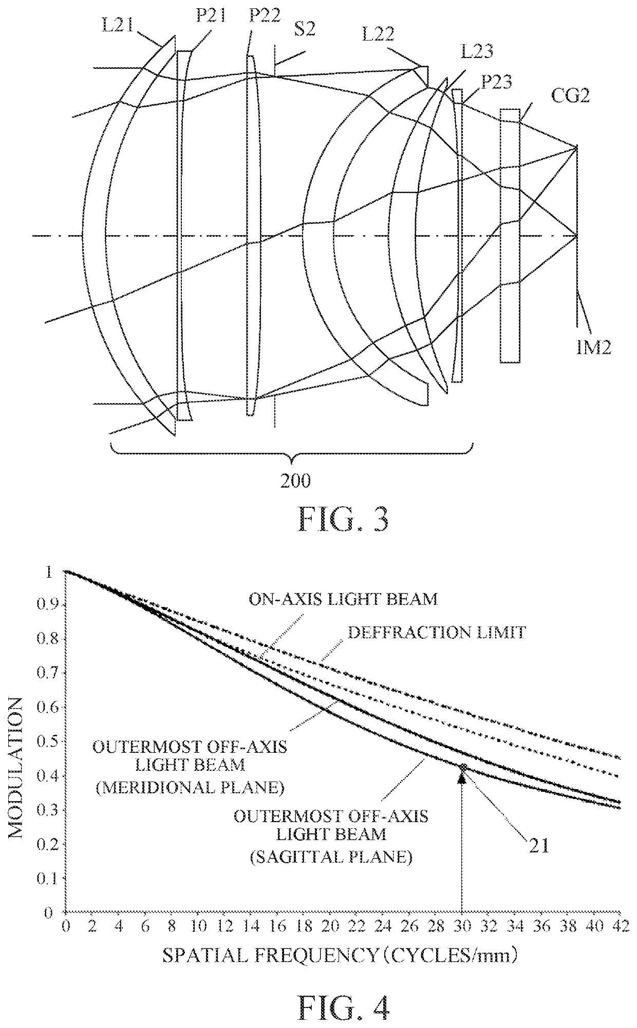
[0057]FIG. 3 is a sectional view of an optical system 200 according to this example. The optical system 200 is an infrared optical system having a focal length of 14 mm and an F-number of 0.8. The optical system 200 includes, in order from the object side to the image side, a first lens L21 having a positive refractive power and made of a silicon material, a thin aspherical plate P21 made of a silicon material and having an aspherical portion with a thickness that gradually increases from the center to the periphery, a thin aspherical plate P22 made of a silicon material and having an aspherical portion with a thickness that gradually decreases from the center to the periphery, a diaphragm S2, a second lens L22 having a positive refractive power and made of a silicon material, a thin lens L23 having a positive refractive power and made of a silicon material, and a thin aspherical plate P23 made of a silicon material and having an aspherical portion with a thickness that gradually in...
example 3
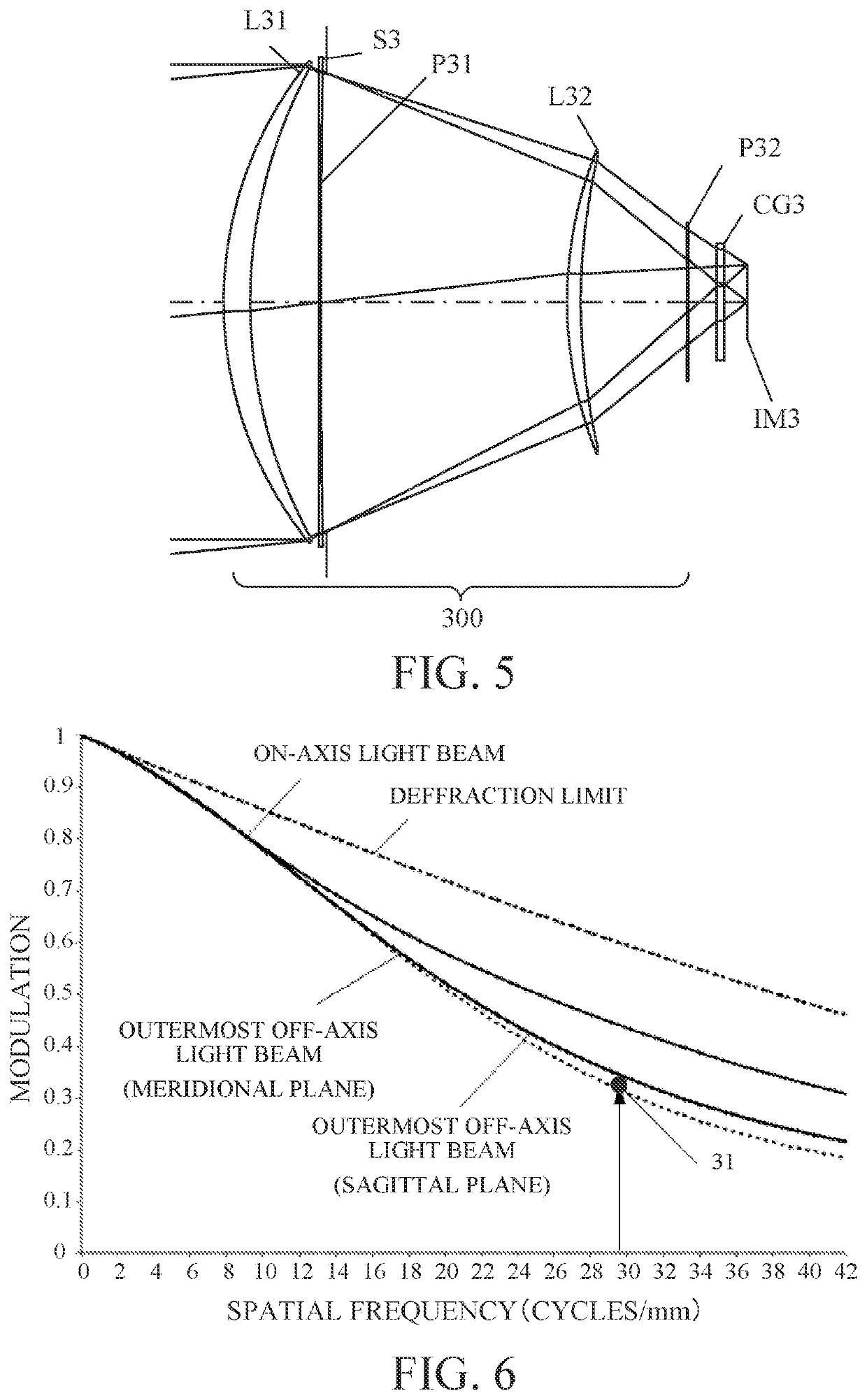
[0060]FIG. 5 is a sectional view of an optical system 300 according to this example. The optical system 300 is an infrared optical system having a focal length of 50 mm and an F-number of 0.8. The optical system 300 includes, in order from the object side to the image side, a first lens L31 made of a silicon material and having a positive refractive power, a thin aspherical plate P31 made of a silicon material and having an aspherical portion with a thickness that gradually increases from the center to the periphery, a diaphragm S3, a second lens L32 having a positive refractive power and made of a silicon material, and a thin aspherical plate P32 made of a silicon material and having an aspherical portion with a thickness that gradually increases from the center to the periphery. Therefore, it can be manufactured by easy processing such as a bending process used to manufacture the Schmidt correction plate. The thin aspherical plates P31 and P32 are assumed to have a very thin thick...
PUM
 Abstract
Description
Claims
Application Information