Connecting structure for hose with corrugated metal tube

Inactive Publication Date: 2005-03-15
TOKAI RUBBER IND LTD
View PDF19 Cites 35 Cited by
  • Summary
  • Abstract
  • Description
  • Claims
  • Application Information

AI Technical Summary

Benefits of technology

According to the present invention, a good seal may be provided on an end portion of the hose with corrugated metal tube, specifically, a connected portion between the hose and the mating pipe without welding operation. Hence, according to the present invention, welding operation may be completely eliminated during production of a hose or connecting a hose to the mating pipe. At the same time, such problem is solved as repeated stress concentration on a welded portion due to vibration, bending or internal pressure load causes breakage of a hose. Further, as welding procedure is eliminated, a hose may be manufactured easier and its production cost may be lowered. Furthermore, as an inner surface of the flared portion of the corrugated metal tube is forced to contact against the outer abutment surface of the mating pipe under fastening force by a fastening member, a sealing property is ensured.
A screw-th

Problems solved by technology

Then it is anticipated difficult to satisfy the future requirements with hoses made only of organic materials such as rubber or resin.
However, as an inner layer, i.e., a corrugated metal tube in the hose with corrugated metal tube is difficult to deform, if the hose with corrugated metal tube is adapted, it will be a problem how to construct fastening or connecting structure on an end portion of the hose with corrugated metal tube so as to assure sealing property thereon.
However, in case of a hose with a corrugated metal tube in or as an inner layer, sufficient close-contact relation is hardly obtained between the corrugated metal tube and the connecting pipe or the connecting part.
If there is a scratch on a surface of the corrugated metal tube in a compressed or swaged range, internal fluid easily leaks out of that scratch.
However, a great deal

Method used


Image

  • Connecting structure for hose with corrugated metal tube
  • Connecting structure for hose with corrugated metal tube
  • Connecting structure for hose with corrugated metal tube

Examples


Example

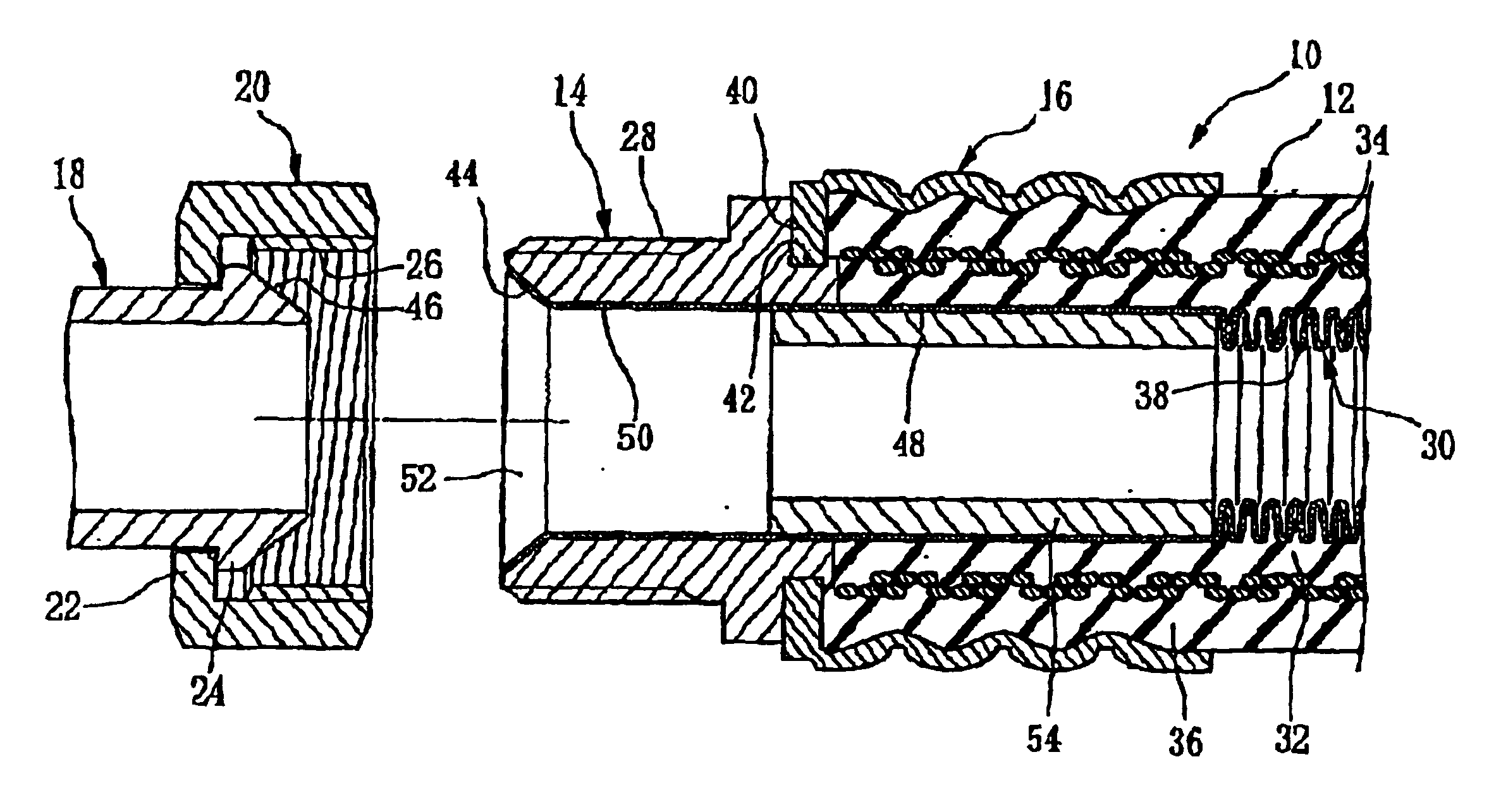
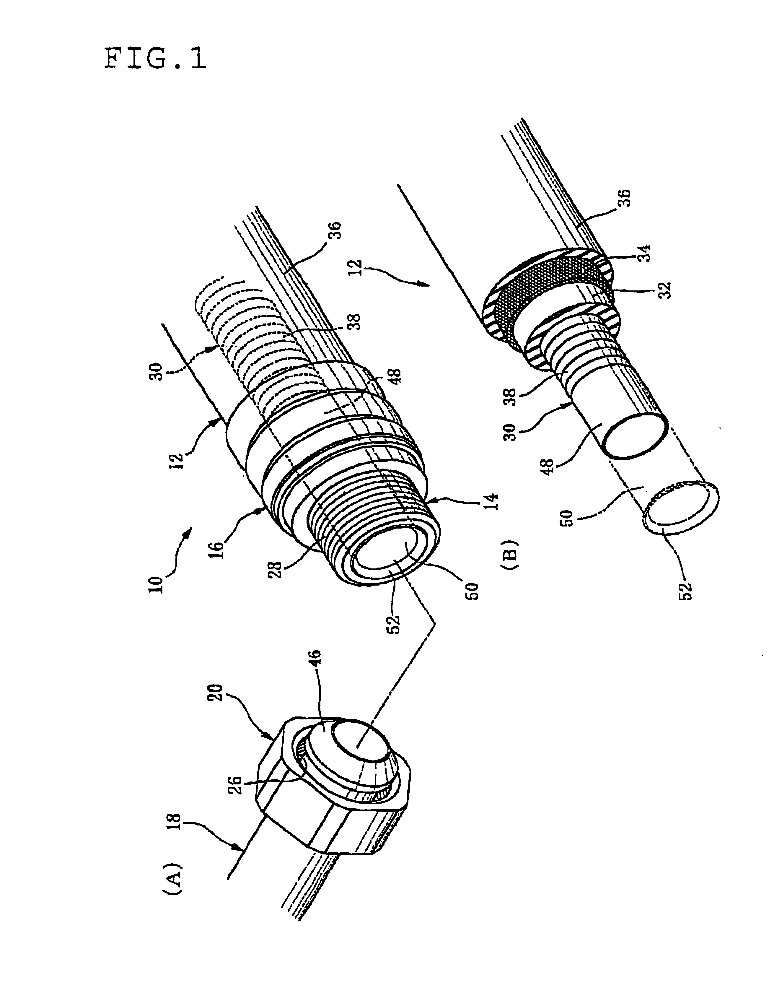
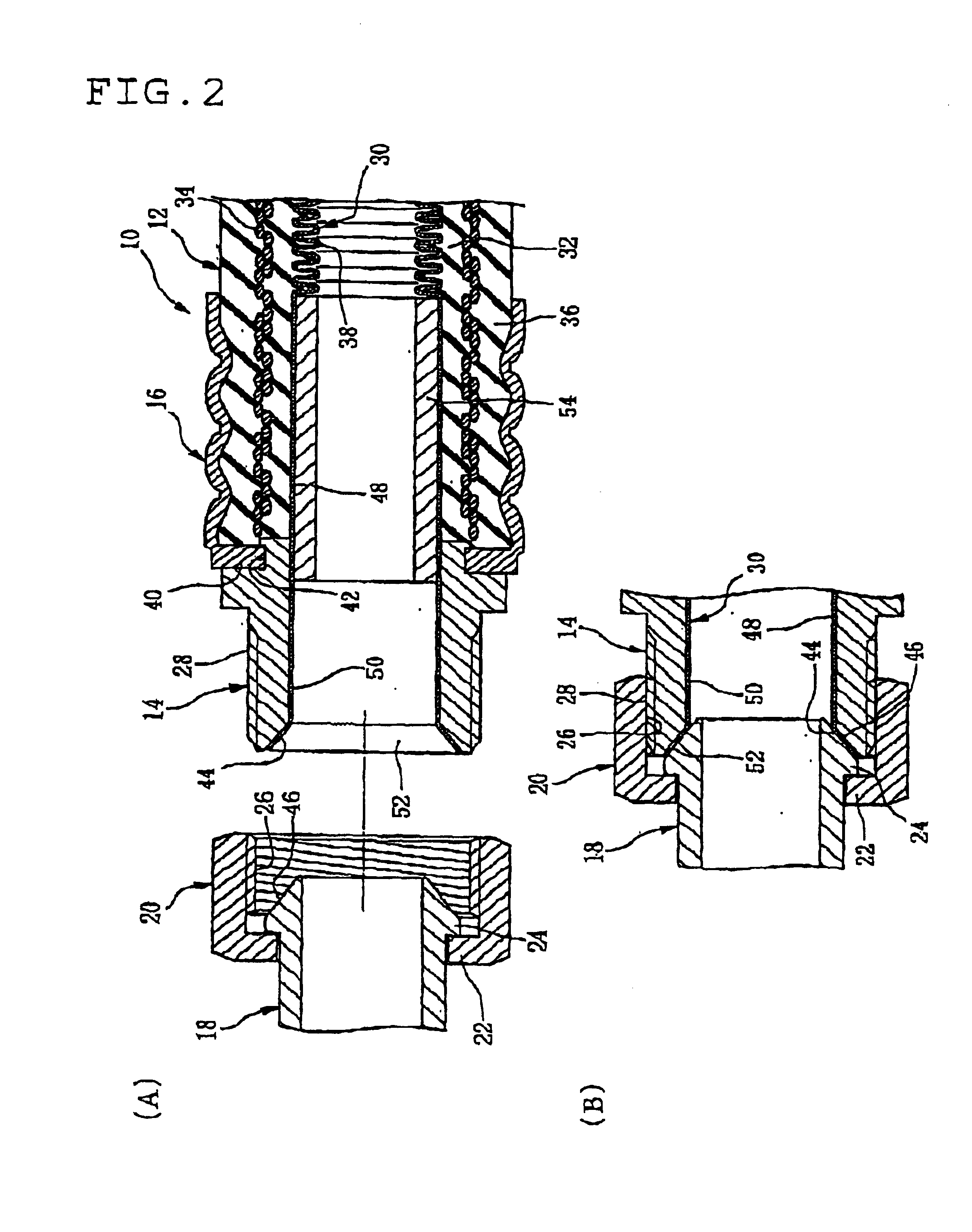
In FIGS. 1 and 2, a numeral reference 10 indicates a hose with corrugated metal tube (hereineafter referred to as a hose) which is preferably adapted for hydrogen or hydrogen gas conveying hose, refrigerant conveying hose for air conditioners, automobile fuel conveying hose or the like. A numeral reference 12 indicates a hose body, a numeral reference 14 a metallic connecting pipe fixed to the hose body 12, a numeral reference 16 a metallic socket fitting fitted onto or on an outer surface of the hose body 12. The socket fitting 16 is securely compressed or swaged to the hose body 12 and thereby the connecting pipe 14 is, along with the socket fitting 16, fixedly secured to the hose body 12.

A numeral reference 18 indicates a metallic mating pipe to be mated with the hose 10. The hose 10 or the hose body 12 is connected to the metallic mating pipe 18 by means of the connecting pipe 14. A numeral reference 20 indicates a cap nut or hexagon cap nut as a screw-thread fastener which fast...


PUM

PropertyMeasurementUnit
Forceaaaaaaaaaa

Abstract

In a hose with corrugated metal tube, a connecting pipe is formed with a tapered inner surface in a tip end portion thereof a corrugated metal tube is formed with a flared portion flaring as to correspond to the tapered inner surface of the connecting pipe, and a mating pipe is formed with a tapered outer surface. The hose with corrugated metal tube is connected to the mating pipe by a cap nut so that the tapered inner space of the connecting pipe abuts the tapered outer surface of the mating pipe with the flared portion therebetween.

Description

CROSS-REFERENCE TO RELATED APPLICATIONThe present application asserts priority on Japanese Patent Application No. 2002-215770 filed Jul. 24, 2002.BACKGROUND OF THE INVENTIONThe present invention relates to a hose with corrugated metal tube, which is suitable for fuel conveying hose for automobiles, refrigerant conveying hose or any other fluid conveying hose, and more particularly to a hose connecting structure for connecting a hose with corrugated metal tube to a mating pipe.Typical rubber hoses, for example, made of blended product of acrylonitrile-butadiene rubber and polyvinyl chloride (NBR / PVC blend) which is excellent in resistance to gasoline permeability, have been used for conveying fuel for automobiles or the like in view of their high vibration-absorbability, easy assembling or the like. However, for the purpose of global environment protection, the regulations have been recently tighten against permeation of fuel for automobiles or the like, and are anticipated to be fur...

Claims


Application Information

Patent Timeline
IPC IPC(8): F16L33/26F16L33/01F16L19/02F16L11/14F16L33/20
CPCF16L33/01F16L33/207F16L33/26F16L33/2076Y10S285/903
Inventor FURATA, NORIHIKO
Owner TOKAI RUBBER IND LTD
Why Eureka
Try Eureka