

Lighting apparatus and display apparatus
- Summary
- Abstract
- Description
- Claims
- Application Information
AI Technical Summary
Benefits of technology
Problems solved by technology
Method used
Image

Examples
first embodiment
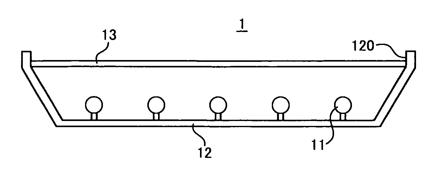
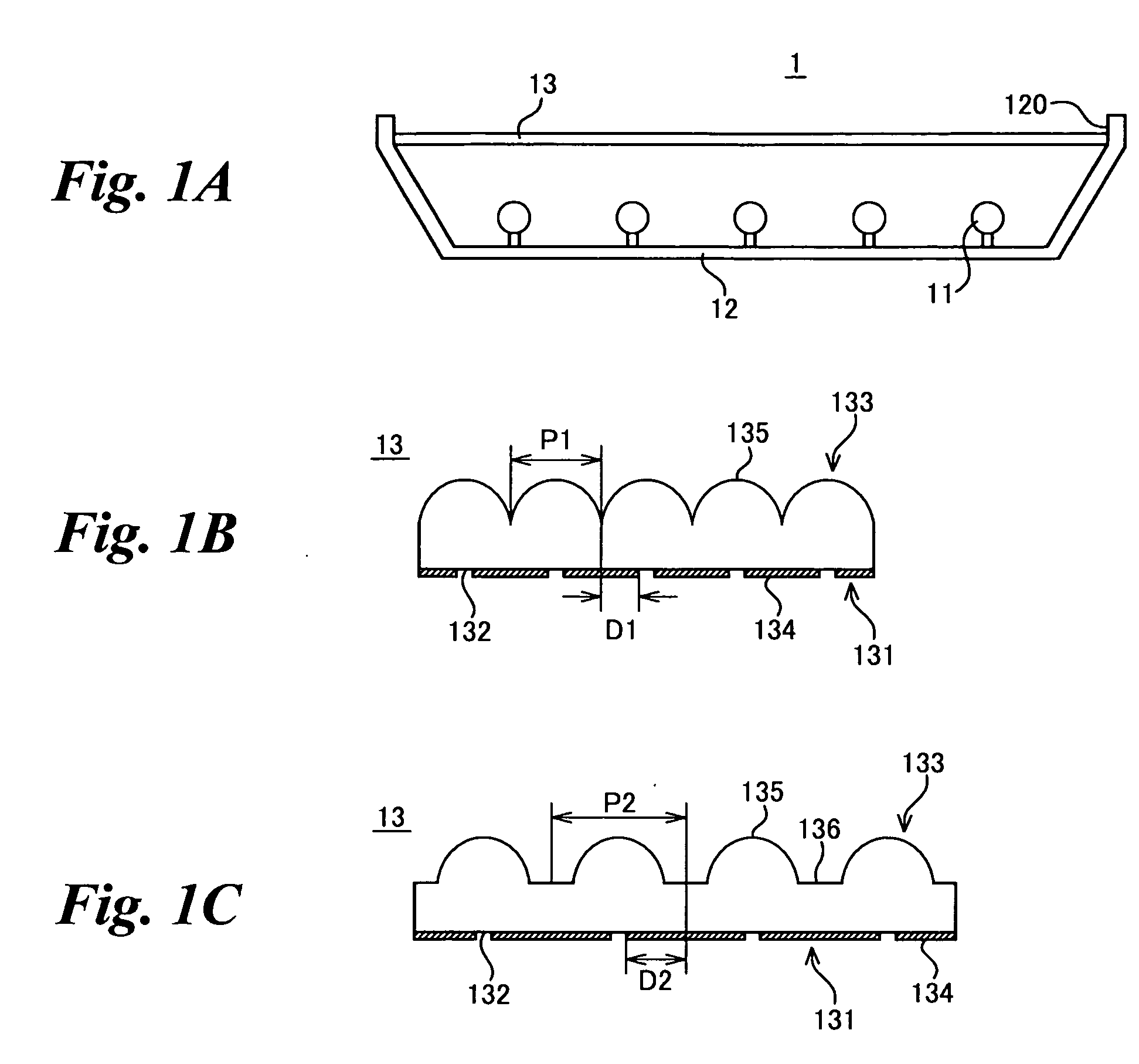
[0066] Overall structure of a lighting apparatus according to the present invention is described hereinafter with reference to FIG. 1A. FIG. 1A schematically illustrates an example of a lighting apparatus according to this invention. As shown in FIG. 1A, the lighting apparatus 1 includes a light source 11, a housing 12 and an optical sheet 13.
[0067] The light source 11 emits light of the lighting apparatus 1 and it may be a fluorescent tube, light emitting diode (LED) and so on.
[0068] The housing 12 has the light source 11 inside, and is provided with a light exit port 120 for outputting the light emitted by the light source 11 to the outside. The inner surface of the housing 12 is formed of a reflective plane that reflects the light from the light source 11 diffusely, and it may be covered with a reflective member such as titanium oxide, for example, so that the entire inner surface of the housing 12 substantially has reflecting properties. Preferably, over 90% of the housing inne...
second embodiment
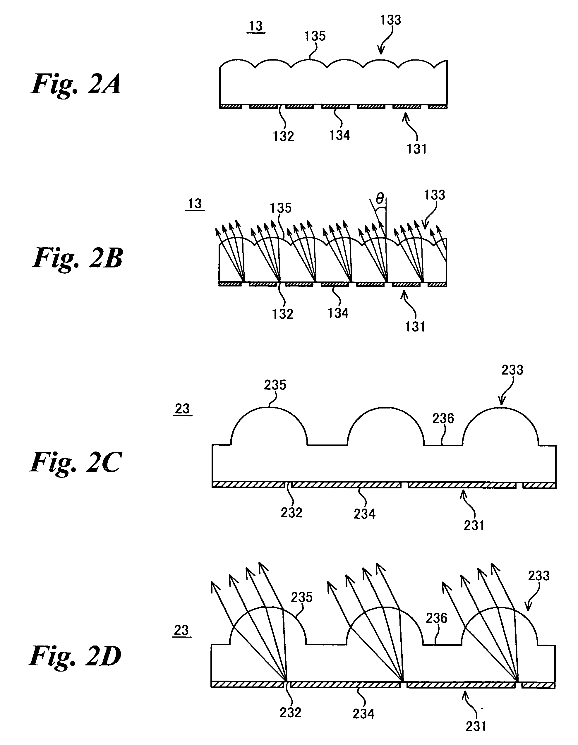
[0084] In the first exemplary embodiment described above, the opening 132 is formed in the vicinity of the optical axis of the lens portion 135 as shown in FIG. 2A to align the optical axes of incident light beams in the normal direction to the optical sheet plane. On the other hand, in a second exemplary embodiment of the present invention, the opening is formed in a position that is slightly off the optical axis of the lens portion 135. In this case, the light beams output from the optical sheet 13 can be aligned in the direction slightly deviated from the normal to the optical sheet plane.
[0085] The direction of incoming light beams is aligned in a given direction by the optical properties of the lens structure 133. Specifically, as shown in FIG. 2B, the light beam is output from the lens portion 135 in a direction inclined with respect to the optical sheet plane in accordance with a degree of deviation of the opening 132 from the optical axis. Thus, the angle of inclination θ b...
third embodiment
[0088] A third exemplary embodiment of the present invention describes another example of optical sheet. The optical sheet of this embodiment has a lens structure having a shape different from the shape of the lens structure of the first embodiment in such a way that the spaces between the lens portions are widened.
[0089] The structure of the optical sheet according to this embodiment is described hereinafter in detail with reference to FIGS. 2C and 2D. FIGS. 2C and 2D are side views that schematically illustrate the optical sheet according to this embodiment.
[0090] As shown in FIG. 2C, the lens structure 233 of the optical sheet 23 of this embodiment has a plurality of flat portions 236 in addition to a plurality of lens portions 235. The flat portions 236 are exemplary non-lens portions that do not substantially have lens effects unlike the lens portions 235. The flat portions 236 form a reflective plane that totally reflects the incident light on the optical sheet 23. Thus, the...
PUM
 Abstract
Description
Claims
Application Information