Eyepiece optical system and imaging apparatus

Active Publication Date: 2015-06-25
FUJIFILM CORP
View PDF5 Cites 3 Cited by
  • Summary
  • Abstract
  • Description
  • Claims
  • Application Information

AI Technical Summary

Benefits of technology

[0033]According to the eyepiece optical system of the present invention, the optical system is composed of three lenses and configured to satisfy given conditional expressions by suitabl

Problems solved by technology

The eyepiece optical systems described in Japanese Unexamined Patent Publication No. 2002-048985, however, can match mostly with small display elements and cannot match with higher

Method used


Image

  • Eyepiece optical system and imaging apparatus
  • Eyepiece optical system and imaging apparatus
  • Eyepiece optical system and imaging apparatus

Examples


Example

Example 1

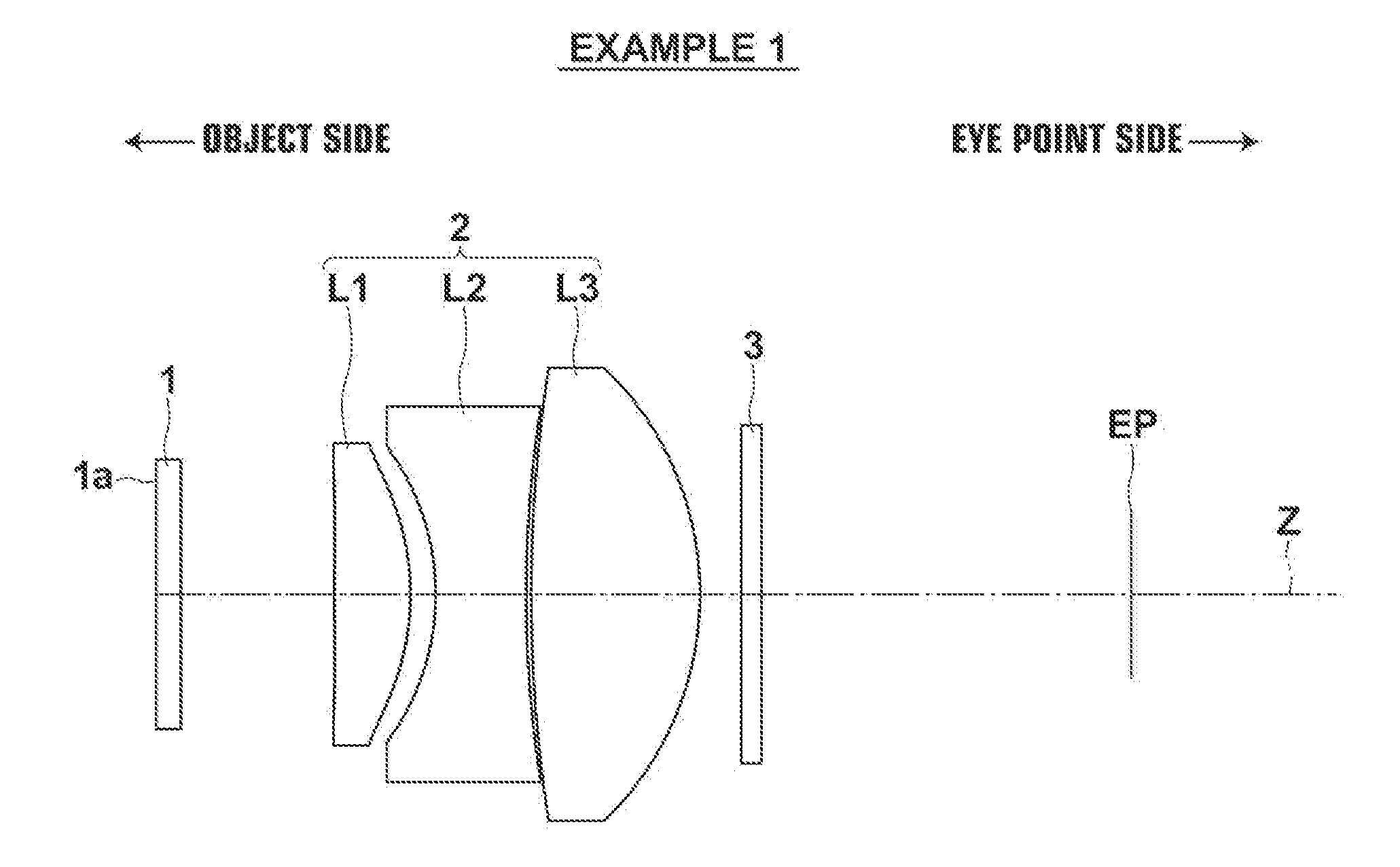
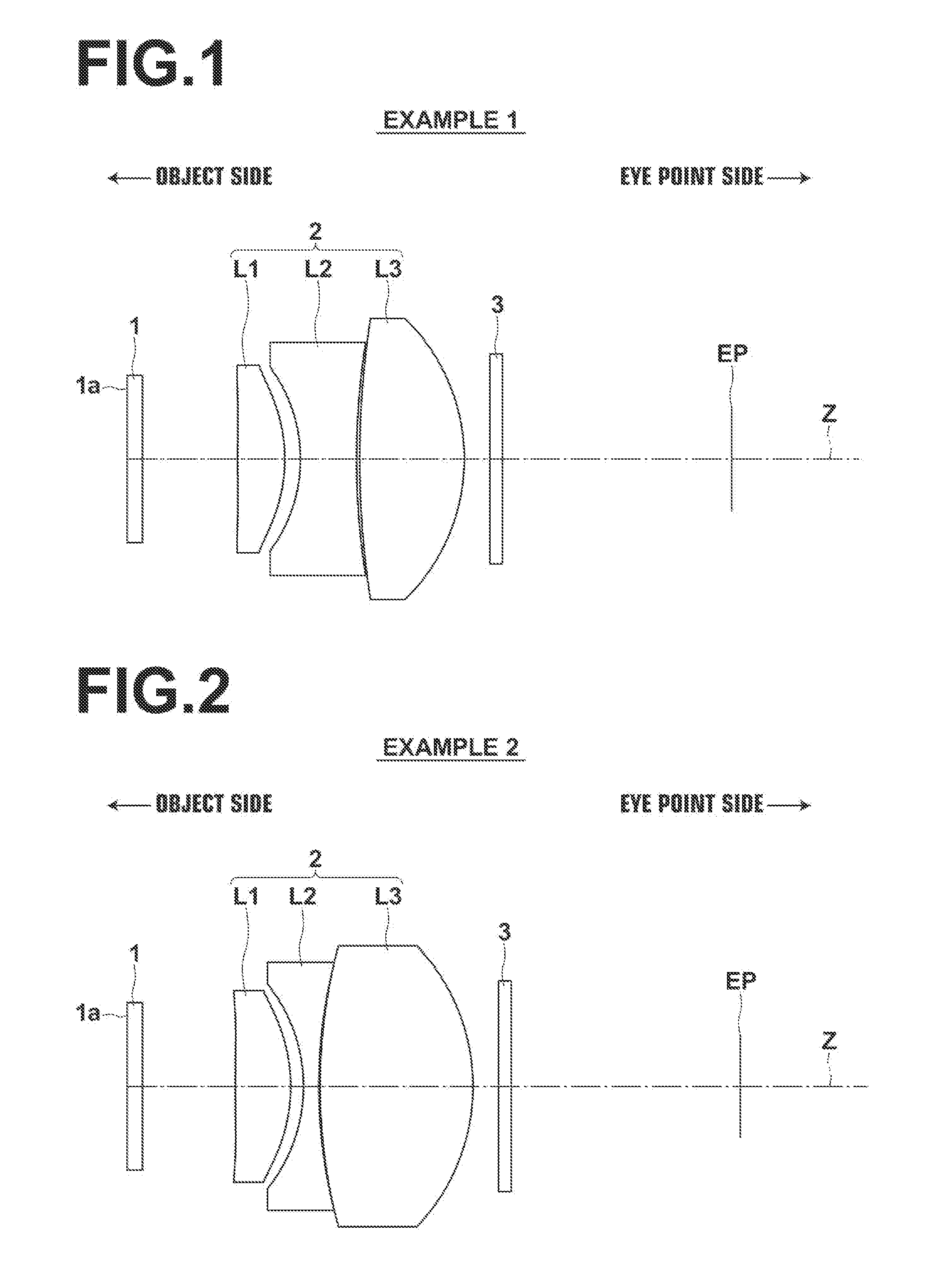
[0086]The lens configuration diagram of the eyepiece optical system of Example 1 is shown in FIG. 1. Tables 1 and 2 show basic lens data and aspherical surface coefficients of the eyepiece optical system of Example 1 respectively. The Si column in Table 1 indicates ith surface number in which a number i (i=1, 2, 3, - - - ) is given to each surface in a serially increasing manner toward the eye point side with the object side surface of the most object side constituent element being taken as the first surface, the Ri column indicates the radius of curvature of ith surface, the Di column indicates the surface distance on the optical axis Z between ith surface and (i+1)th surface, the Ndj column indicates the refractive index of jth optical element from the object side with respect to the d-line (wavelength of 587.56 nm) and the vdj column indicates the value of the Abbe number of jth optical element from the object side with respect to the d-line.

[0087]The basic lens data als...

Example

Example 2

[0096]The lens configuration diagram of the eyepiece optical system of Example 2 is shown in FIG. 2. Tables 3 and 4 show basic lens data and aspherical surface coefficients of the eyepiece optical system of Example 2 respectively. FIG. 6 shows aberration diagrams of the eyepiece optical system of Example 2, in which diagrams of spherical aberration, astigmatism, distortion, and lateral chromatic aberration are arranged from the left in the drawing.

TABLE 3Example 2 Basic Lens DataSiRiDiNdjν dj1∞1.2001.5168064.202∞7.300*3101.33324.3501.8034840.45*4−12.92271.0005−12.74011.2001.9590617.47639.36300.100742.765012.001.9537532.328−15.9262

TABLE 4Example 2 Aspherical Surface CoefficientSi34KA1.00000E+001.00000E+00A3−2.73581E−03 −1.82043E−03 A41.26698E−031.15295E−03A5−2.22912E−04 −2.45870E−04 A6−5.47948E−07 1.74095E−05A71.83598E−065.90827E−07A89.54297E−083.01143E−08A9−1.56329E−08 −3.75556E−08 A101.41396E−094.13819E−09A11−3.66838E−10 −1.26579E−12 A12−2.37782E−11 −2.52905E−11 A134.75026...

Example

Example 3

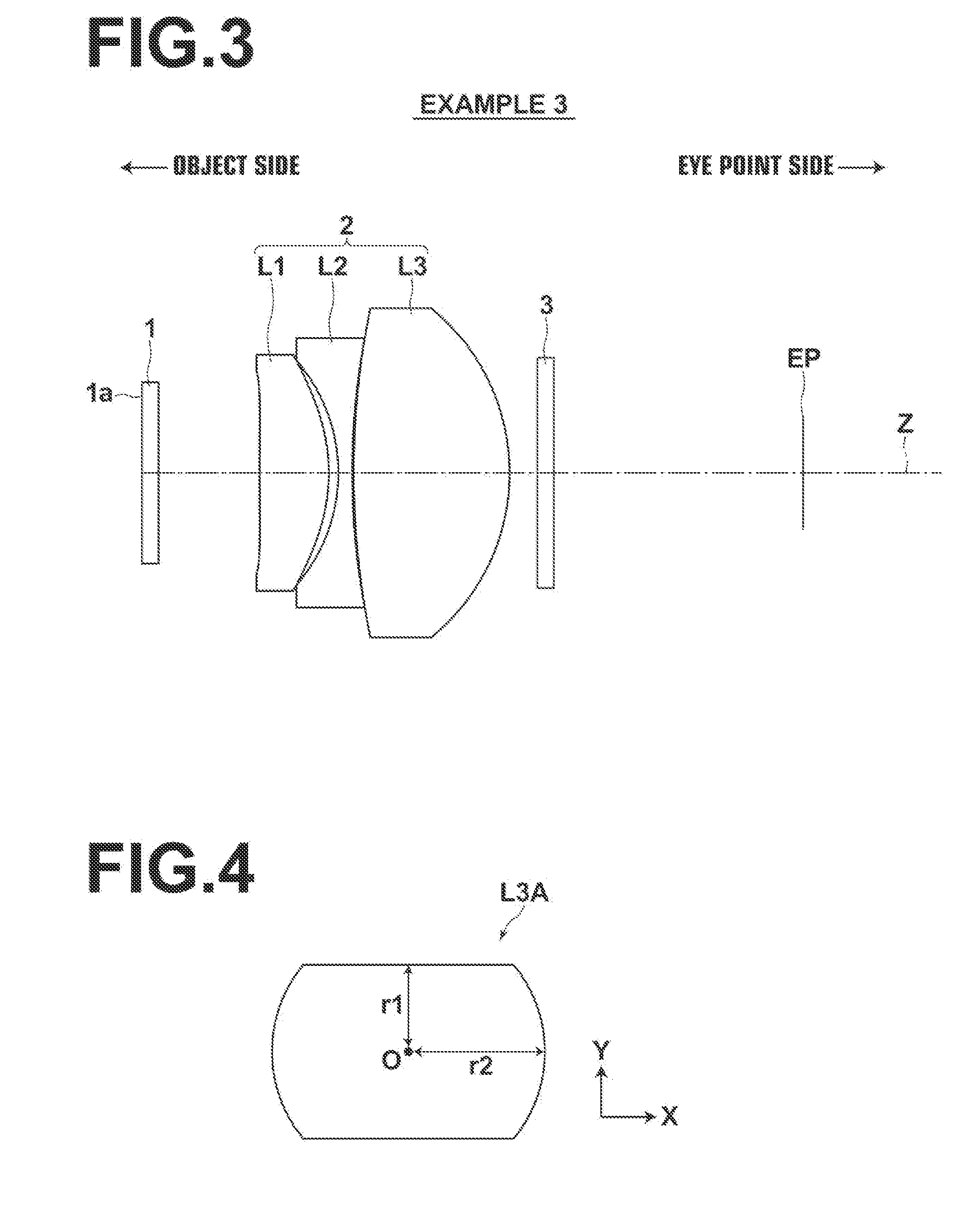
[0097]The lens configuration diagram of the eyepiece optical system of Example 3 is shown in FIG. 3. Tables 5 and 6 show basic lens data and aspherical surface coefficients of the eyepiece optical system of Example 3 respectively. FIG. 7 shows aberration diagrams of the eyepiece optical system of Example 3, in which diagrams of spherical aberration, astigmatism, distortion, and lateral chromatic aberration are arranged from the left in the drawing.

TABLE 5Example 3 Basic Lens DataSiRiDiNdjν dj1∞1.2001.5168064.202∞7.300*3156.15905.0001.8022040.68*4−12.94760.6895−12.32931.0001.9590617.47652.30500.107759.203411.2501.9537532.328−15.2769

TABLE 6Example 3 Aspherical Surface CoefficientSi34KA 1.00000E+00 1.00000E+00A3−5.55255E−04−1.52493E−04A4 1.07449E−04 1.70504E−04A5−6.39124E−05−5.18737E−05A6 1.80882E−05 1.80618E−05A7−1.49474E−06−1.89724E−06A8−1.55902E−07−6.93500E−08A9−6.38619E−09−2.26611E−08A10 4.60347E−09 6.54891E−09A11−8.04934E−11 1.84786E−10A12−6.55930E−11 2.13778E−12A13 9.612...


PUM


Abstract

An eyepiece optical system substantially composed of a first lens having a positive refractive power with a convex surface on the eye point side, a second lens having a negative refractive power with a concave surface on the object side, and a third lens having a positive refractive power with an absolute value of radius of curvature of the eye point side surface being smaller than an absolute value of radius of curvature of the object side surface, disposed in order from the object side. The first lens to the third lens are all single lenses and, when the average refractive index of the first lens to the third lens is taken as NdH, the eyepiece optical system satisfies a conditional expression (1): 1.80<NdH.

Description

CROSS-REFERENCE TO RELATED APPLICATIONS[0001]The present application claims priority under 35 U.S.C. §119 to Japanese Patent Application No. 2013-263499 filed on Dec. 20, 2013 and Japanese Patent Application No. 2014-226576 filed on Nov. 7, 2014. Each of the above applications is hereby expressly incorporated by reference, in their entirety, into the present application.BACKGROUND OF THE INVENTION[0002]1. Field of the Invention[0003]The present invention relates to an eyepiece optical system and an imaging apparatus, and more specifically to an eyepiece optical system that can be used favorably for the observation of an image displayed on a display screen, and an imaging apparatus equipped with the eyepiece optical system.[0004]2. Description of the Related Art[0005]Heretofore, eyepiece optical systems that magnify images displayed on display screens such as, for example, liquid crystal display elements, for observing the images with naked eyes have been used for viewfinders of vide...

Claims


Application Information

Patent Timeline
IPC IPC(8): G02B25/00
CPCG02B25/001H04N23/55
Inventor SATO, KENICHI
Owner FUJIFILM CORP
Why Eureka
Try Eureka